Any spec on performance is already out there anyway, on their own website, downloadable in excel ") It probably sais more than the datasheet...
It probably sais more than the datasheet...
They also provide a free schematic of the ESS website. You could even copy that and have a DAC without the need of a datasheet if you wanted.
A few days ago, this link somewhere on this thread did actually still work, so I'm guessing it still does. If ESS does not want it public I suggest that the link is removed. I'd sign an NDA if I need to.. no problem.
Imho the datasheet does not contain any shocking information that should be hidden from the public, so I guess that Russ is right in saying that it's not public because it's preliminary..
It probably sais more than the datasheet...They also provide a free schematic of the ESS website. You could even copy that and have a DAC without the need of a datasheet if you wanted.
A few days ago, this link somewhere on this thread did actually still work, so I'm guessing it still does. If ESS does not want it public I suggest that the link is removed. I'd sign an NDA if I need to.. no problem.
Imho the datasheet does not contain any shocking information that should be hidden from the public, so I guess that Russ is right in saying that it's not public because it's preliminary..
To people waiting for my board: it will take a bit more time to complete it.
Why?
Just because I have to fix my *&#$ computer.
The new hard drive was in my mailbox this morning, I'm trying to rescue all my data :'(
I'll now stop polluting this thread - but be sure that I'm working on it.
When the projet will be ready - just to check again everything, I'll post a new thread.
Thanks,
Nicolas
Denon DVD-1920 DSD MOD
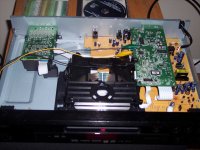
OK for those of you who don't mind risking a Denon DVD-1920 and want to get DSD out of it...
Here is how I am doing it:
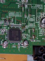
There are three vias at DBK,DSD1,DSD2. Solder a tiny wire into each via.
I am not sure how I will run these to the panel, but for now just to test the DAC I just used allegator clip jumpers to wires which are installed in the DAC.
It actually sounds very good despite the makeshift wiring! It is definitely much better than the stock DAC, but that would not actually take much.
The DVD-1920 is much easier to modify than the DVD2910, so I would go that route personally.
Cheers!
Russ
Here is a picture of the wires soldered into the whiskers.
OK for those of you who don't mind risking a Denon DVD-1920 and want to get DSD out of it...
Here is how I am doing it:
There are three vias at DBK,DSD1,DSD2. Solder a tiny wire into each via.
I am not sure how I will run these to the panel, but for now just to test the DAC I just used allegator clip jumpers to wires which are installed in the DAC.
It actually sounds very good despite the makeshift wiring! It is definitely much better than the stock DAC, but that would not actually take much.
The DVD-1920 is much easier to modify than the DVD2910, so I would go that route personally.
Cheers!
Russ
Here is a picture of the wires soldered into the whiskers.
Attachments
MrMajestic said:Great posts Russ, just what I was looking for
Edit:
Would pin 46,47 and 50 get me PCM output and could I run that to TP SPDIF module?
Hello,
I have not tested PCM to SPDIF on this player yet, but it looks like you will want to take the PCM signal from:
PLRCK (51) - Left/Right clock
PBCK (50) - Bit Clock
PDATA1 (46) - PCM DATA for channels 1 and 2 (Usually front left and right).
I am not sure the format yet, I will let you know when I try it.
Cheers!
Russ
MrMajestic said:
I mean that a proper layout of this chip needs a plane for GND, a plane for the analog VCC, and a plane for the core voltage, because of the way the power pins are placed, which is slightly too much for 2 layers, you'd need 4 layers.
However 2 layers will work, you probably won't get the ludicrously high crosstalk performance figures in the datasheet, but you'll probably still get high performance, and as long as it sounds good...
I'm not blaming Dustin 'cause the way the power pins are placed around the chip really makes sense, I stand in awe just looking at the pinout thinking "damn, someone finally got it right". So, congrats.
Now, Dustin, can you please add a differential clock input ? There are NC pins there, use them, I mean all the high-perf instrumentation DACs have differential clock inputs (for good reason), PLEASE be the first to introduce this for audio, I'll build you a shrine, I'll immolate chickens in the name of ya, I'll drive to your place with a pack o'beer, but please, give me that differential clock input which is basically the only way to achieve ultra low jitter without massive design headaches.
I did not have any issues routing the board 2 layer, and I think the routing is very good. if anything it forced me to carefully think about the GND and power returns. We will see how it measures. Personally I don't see the need for a 4 layer board in the least.
Cheers!
Russ
Cheers!
Russ
peufeu said:
Now, Dustin, can you please add a differential clock input ? There are NC pins there, use them, I mean all the high-perf instrumentation DACs have differential clock inputs (for good reason), PLEASE be the first to introduce this for audio, I'll build you a shrine, I'll immolate chickens in the name of ya, I'll drive to your place with a pack o'beer, but please, give me that differential clock input which is basically the only way to achieve ultra low jitter without massive design headaches.
You owe me a new keyboard
and I second the emotion: although Dustin had mentioned that there are no analog bias lines inside the chip; an LVDS or PECL diff clock input would be XLNT, and that small amount of (internal to the chip) analog circuitry could be done without breaking the design integrity. Rev C? The chip is already good, that would be gooder. That and adding a mono input mode. And disabling automute so that a standalone HW mode would be practical. Paging Dustin...?
Russ White said:
Hello,
I have not tested PCM to SPDIF on this player yet, but it looks like you will want to take the PCM signal from:
PLRCK (51) - Left/Right clock
PBCK (50) - Bit Clock
PDATA1 (46) - PCM DATA for channels 1 and 2 (Usually front left and right).
I am not sure the format yet, I will let you know when I try it.
Cheers!
Russ
Ah yes, pin 47 is not correct, must have been tired
Would be great if this worked.wildmonkeysects said:
You owe me a new keyboard
Paging Dustin...?
Haha.
Actually Xilinx gets ridiculously low jitter (useful for über-gigabit speeds) in their humongously expensive Virtex-5 by putting differential clock lines ON THE DIE.
peufeu said:
I mean that a proper layout of this chip needs a plane for GND, a plane for the analog VCC, and a plane for the core voltage, because of the way the power pins are placed, which is slightly too much for 2 layers, you'd need 4 layers.
However 2 layers will work, you probably won't get the ludicrously high crosstalk performance figures in the datasheet, but you'll probably still get high performance, and as long as it sounds good...
I'm not blaming Dustin 'cause the way the power pins are placed around the chip really makes sense, I stand in awe just looking at the pinout thinking "damn, someone finally got it right". So, congrats.
Now, Dustin, can you please add a differential clock input ? There are NC pins there, use them, I mean all the high-perf instrumentation DACs have differential clock inputs (for good reason), PLEASE be the first to introduce this for audio, I'll build you a shrine, I'll immolate chickens in the name of ya, I'll drive to your place with a pack o'beer, but please, give me that differential clock input which is basically the only way to achieve ultra low jitter without massive design headaches.
Hi Peufeu,
The Xtalk number we post in the datasheet are derived from a 2 layer board. To my knowledge there has been no 4 layer board for this chip yet. I just wanted to point that out.
Thanks
Dustin
- Home
- Source & Line
- Digital Line Level
- ESS Sabre Reference DAC (8-channel)