I would like to convert from left-justified I2S to an I2S format compatible with TDA1541A(let's call it Philips I2S)
Please see this datasheet, page 6:
http://www.analog.com/UploadedFiles/Data_Sheets/AD1852.pdf
(conversion from the format in figure 3 to the format in figure 2)
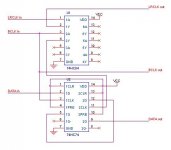
The question is whether the attached schematic would do it in a problem free manner. Also, does anyone in here prefer some manufacturers over the others when it comes to these logic chips?
Please see this datasheet, page 6:
http://www.analog.com/UploadedFiles/Data_Sheets/AD1852.pdf
(conversion from the format in figure 3 to the format in figure 2)
The question is whether the attached schematic would do it in a problem free manner. Also, does anyone in here prefer some manufacturers over the others when it comes to these logic chips?
Attachments

")
I don't think this is a good solution.
How much delay would you expect from 74hc4d and 74hc4e? I see no effect in addition 74hc4d and 74hc4e before 74hc74.
You still have the same problem of timing relationship between SDATA out and BCLK. 1Q is updated right after rising edge of BCLK. This mean that DATA out is only valid after rising edge of BCLK. Your desired format require that rising edge of BCLK is somewhere around the middle of DATA.
To deal with this problem, you may see that I recommended to invert BCLK for the 2nd half of 74HC74 in the schematic. Each half of the 74hc74 cause a delay of 1/2 BCLK cycle. I am pretty sure about the logic but I have not tried it therefore ...
curva said:So what about this? Double inverting for delay than flip flop
How much delay would you expect from 74hc4d and 74hc4e? I see no effect in addition 74hc4d and 74hc4e before 74hc74.
You still have the same problem of timing relationship between SDATA out and BCLK. 1Q is updated right after rising edge of BCLK. This mean that DATA out is only valid after rising edge of BCLK. Your desired format require that rising edge of BCLK is somewhere around the middle of DATA.
To deal with this problem, you may see that I recommended to invert BCLK for the 2nd half of 74HC74 in the schematic. Each half of the 74hc74 cause a delay of 1/2 BCLK cycle. I am pretty sure about the logic but I have not tried it therefore ...
Yes it may work if you are lucky.
Why?
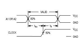
In both schematic, data is delayed by 1/2 BCLK cycle plus the propagation delay caused by the logic chip. Propagation delay time is given in datasheet as max limit only. In fact propagation delay time is normally shorter than max limit and also depends on brand of logic IC so we do not know exactly whether the propogation delay time is long enough for the receiving IC to work.
For mc74hc164 made by motorola propogation delay time is as attached.
Why?
In both schematic, data is delayed by 1/2 BCLK cycle plus the propagation delay caused by the logic chip. Propagation delay time is given in datasheet as max limit only. In fact propagation delay time is normally shorter than max limit and also depends on brand of logic IC so we do not know exactly whether the propogation delay time is long enough for the receiving IC to work.
For mc74hc164 made by motorola propogation delay time is as attached.
Attachments
Re: Re: Left-justified I2S to Philips I2S Converter
Ok, "left-justified" mode. If the name doesn't tell the story you can always look at the datasheet.
rfbrw said:
Doesn't exist.
Ok, "left-justified" mode. If the name doesn't tell the story you can always look at the datasheet.
Re: Re: Re: Left-justified I2S to Philips I2S Converter
Presumably under the section titled " Square circle".
curva said:
Ok, "left-justified" mode. If the name doesn't tell the story you can always look at the datasheet.
Presumably under the section titled " Square circle".
Re: Re: Re: Re: Left-justified I2S to Philips I2S Converter
Actually it is under "Serial Data Input Mode", pages 6 and 7.
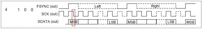
As about it not being an I2S signal, I believe you can look at it as being I2S where the MSB of the input signal is being dropped/ignored, LSB=0 and the channels are inverted. If you find these names inappropriate, care to tell us what it's name really is?
rfbrw said:
Presumably under the section titled " Square circle".
Actually it is under "Serial Data Input Mode", pages 6 and 7.
As about it not being an I2S signal, I believe you can look at it as being I2S where the MSB of the input signal is being dropped/ignored, LSB=0 and the channels are inverted. If you find these names inappropriate, care to tell us what it's name really is?
I could understand what curva needs by reading the following. Even it could be called "left justified", the format in figure 3 is slightly different from the "left justified" format of CS8412 or CS8414.
curva said:
Please see this datasheet, page 6:
http://www.analog.com/UploadedFiles/Data_Sheets/AD1852.pdf
(conversion from the format in figure 3 to the format in figure 2)
Indeed, I was also wondering about it being slightly different than what a CS84* puts out.
Quantran, many thanks for all your help with this, I clearly need to read some more on the subject, I really want to understand it.
For now I want to hook up the signal to my scope see how many BCLK per WCLK there are(I don't have a logic analyzer) and the timings. The signal is not produced by a CS chip, it comes off a FPGA.
- Status
- This old topic is closed. If you want to reopen this topic, contact a moderator using the "Report Post" button.
- Home
- Source & Line
- Digital Line Level
- Left-justified I2S to Philips I2S Converter