Hi All!
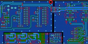
Recently i finished the design of a new control board for a summing mixer.
This control board features led vumeter drivers LM3915 and rectifiers (see the picture at left side), and an analog monitoring section (right side of the picture).
As i want to separate the currents of the two sections, i placed the Ground point in the middle and cut out the top and bottom copper to steer the return currents, and avoid to mix them...
This is my first try on this... so i want to know if i placed the ground point correctly...
Besides, i placed a lot of stitching vias... these vias as far as i was told.. add capacitance... and help lower the noise in the ground plane.. I placed them more or less randomly on the corners and sides... I suppose this is correct...
Any comment on Single Point Ground and vias are wellcome!
Thank you very much!
Jay X.
Attachments
Hi!
Well, after asking and showing what i did, it seems to be ok. The key is that both sides are at the same potential, or feed by the same supply voltages.
Adding vias helps reducing capacitance and improves shielding against RFI. Otherwise, without vias, big copper areas would behave like a big capacitor...and from there, i don't understand very well what happens...
¡¡Thanks for watching!!
Jay X
- Status
- This old topic is closed. If you want to reopen this topic, contact a moderator using the "Report Post" button.