After many years of cutting raw PC boards to size with a hack saw or Dremel tool I finally
got the courage to try a cut on my table saw - it cut clean and easily like butter. I thought
for years that the PC board being metal would be too tough or damaging to the blade. I
used an old blade and have never had a problem, not that I do much cutting. One time I
accidentally had the blade too low so that it cut through the copper and only slightly into
the fiberglass - interesting that the cut was very clean.
The thought to cut the copper away to "etch" a board has been on my mind for about
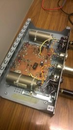
10 years - obviously it has to be a simple board. Recently, I wanted to build a simple
dual regulator to replace the power supply board in a Heath IG-18 and doodled
out a layout late one night with pencil and graph paper. Then thought it is simple
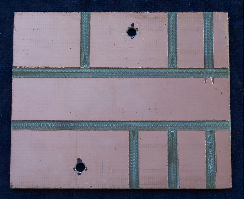
enough to do by cutting the copper on the table saw. Please always wear eye, hearing,
and breathing protection as you always should when operating power tools if you decide
to try this. Protecting your lungs is most important when cutting into glass fiber material,
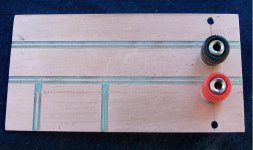
in fact you should not do this unless you wear such protection. Picture of "routed" board:
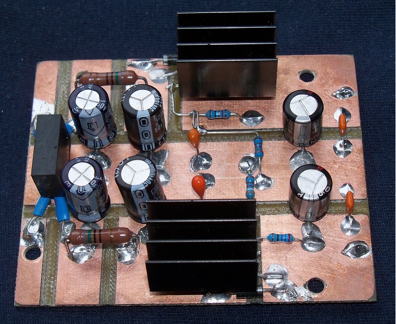
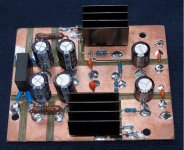
Picture of final assembled board, note the use of through hole components that are
surface soldered to save the time and tedium of drilling holes - thanks to Bernie Hutchins
for this idea:
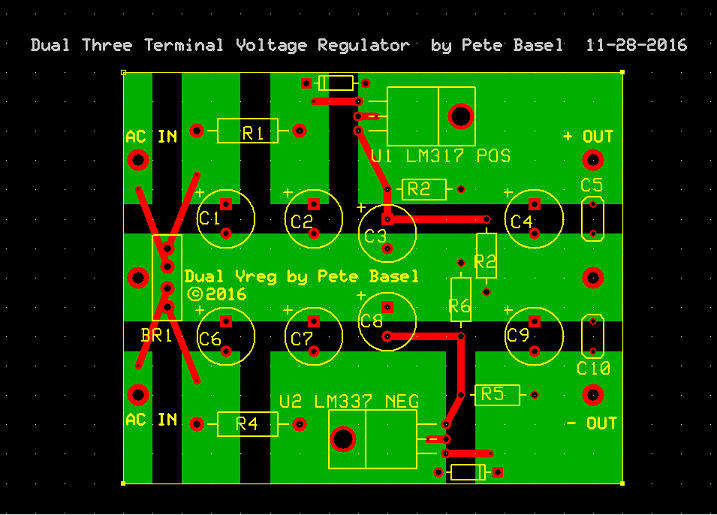
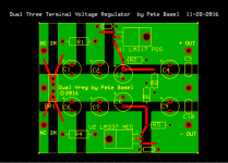
I mostly doodled the layout on graph paper, but then decided after actually making the
board to enter the design into the easy to use Express PCB. This is not a manufacturable
board as shown, rather it is just to have a clear picture. On the other hand it could easily
be made into a manufactured board without needing any jumpers. Note that the green is
circuit board copper and red traces are the component leads in the air. This is not the normal
Express PCB convention for colors:
The pictures essentially show the idea but I'd like to offer a bit more on the thinking behind this:
Leave More Metal:
First, concerning high current PC designs such as power supplies. I've always believed
that what we really want is for the removed metal to be small with as much copper left
behind as possible for low resistance and inductance. This also gets the most mileage
from etchant chemicals when you are DIYing boards.
Surface Soldering:
Drilling holes in DIY PC boards is a slow and tedious job, my Masters project adviser
(Bernie Hutchins) who did a lot of building said why not bend the leads out with DIP
packages and "surface" mount what are normally through hole parts. This is mostly
what I did for this design. Bernie had been doing it for many, many years back in the 1980s.
Ground Plane and Component Leads as Vias:
It makes sense to use dual sided board for simple DIY boards like this and just leave
one side as ground to lower the inductance of the ground connections on the other side
and to provide a means to pick up ground anywhere on the top side by drilling through.
This design, with a wide ground trace down the middle didn't need the ground plane but
I used one just to show how it can be done. Join the ground on the top side by drilling
some of the ground leads and solder them both on top and bottom. All the electrolytic
cap grounds are done this way in this design. 8 holes were drilled not counting the
holes for mechanical support.
Thermal Considerations:
I am often surprised to see insulators being used on small devices such as TO-220
package types when there is just a small heat sink on the circuit board. Make the copper
under the device the tab connection then no insulator is needed either if the device is
mounted flush against the board or directly to the heatsink. The insulator introduces
thermal resistance and degrades the thermal performance.
In this design I've mounted the TO-220 devices tab up so that one screw can be used to
mount both the heat sink and the device, no insulator is used between the package and
heatsink. A small spacer is required to keep the TO-220 devices from rocking over.
I used a #10 nut rather than having to stack several washers for enough height. The
4-40 screw goes right through the #10 nut. A plastic washer is required under the screw
head since the heatsink is hot and a ground plane is used on the back side of the board.
I've never seen this done before with devices mounted tab up.
Finally, there are 3 component leads for each regulator that do not connect to any of the
large area copper planes on the board, they are in the air as is done with simple point to
point wiring. I've tried to locate these over the spaces where copper has been cut away
but it is not absolutely necessary since the air gap alone is good enough. Note that this
layout also works with professional or DIY fabrication methods simply by running a trace
in the open space to connect the 3 components to the regulator adjust pins.
I like being able to go down to the workshop with blank PC board and having a board ready
for soldering in less than an hour.
Minimus 7 Speaker Crossover Board:
http://www.diyaudio.com/forums/cons...ype-pc-boards-etch-table-saw.html#post4938455
got the courage to try a cut on my table saw - it cut clean and easily like butter. I thought
for years that the PC board being metal would be too tough or damaging to the blade. I
used an old blade and have never had a problem, not that I do much cutting. One time I
accidentally had the blade too low so that it cut through the copper and only slightly into
the fiberglass - interesting that the cut was very clean.
The thought to cut the copper away to "etch" a board has been on my mind for about
10 years - obviously it has to be a simple board. Recently, I wanted to build a simple
dual regulator to replace the power supply board in a Heath IG-18 and doodled
out a layout late one night with pencil and graph paper. Then thought it is simple
enough to do by cutting the copper on the table saw. Please always wear eye, hearing,
and breathing protection as you always should when operating power tools if you decide
to try this. Protecting your lungs is most important when cutting into glass fiber material,
in fact you should not do this unless you wear such protection. Picture of "routed" board:
Picture of final assembled board, note the use of through hole components that are
surface soldered to save the time and tedium of drilling holes - thanks to Bernie Hutchins
for this idea:
I mostly doodled the layout on graph paper, but then decided after actually making the
board to enter the design into the easy to use Express PCB. This is not a manufacturable
board as shown, rather it is just to have a clear picture. On the other hand it could easily
be made into a manufactured board without needing any jumpers. Note that the green is
circuit board copper and red traces are the component leads in the air. This is not the normal
Express PCB convention for colors:
The pictures essentially show the idea but I'd like to offer a bit more on the thinking behind this:
Leave More Metal:
First, concerning high current PC designs such as power supplies. I've always believed
that what we really want is for the removed metal to be small with as much copper left
behind as possible for low resistance and inductance. This also gets the most mileage
from etchant chemicals when you are DIYing boards.
Surface Soldering:
Drilling holes in DIY PC boards is a slow and tedious job, my Masters project adviser
(Bernie Hutchins) who did a lot of building said why not bend the leads out with DIP
packages and "surface" mount what are normally through hole parts. This is mostly
what I did for this design. Bernie had been doing it for many, many years back in the 1980s.
Ground Plane and Component Leads as Vias:
It makes sense to use dual sided board for simple DIY boards like this and just leave
one side as ground to lower the inductance of the ground connections on the other side
and to provide a means to pick up ground anywhere on the top side by drilling through.
This design, with a wide ground trace down the middle didn't need the ground plane but
I used one just to show how it can be done. Join the ground on the top side by drilling
some of the ground leads and solder them both on top and bottom. All the electrolytic
cap grounds are done this way in this design. 8 holes were drilled not counting the
holes for mechanical support.
Thermal Considerations:
I am often surprised to see insulators being used on small devices such as TO-220
package types when there is just a small heat sink on the circuit board. Make the copper
under the device the tab connection then no insulator is needed either if the device is
mounted flush against the board or directly to the heatsink. The insulator introduces
thermal resistance and degrades the thermal performance.
In this design I've mounted the TO-220 devices tab up so that one screw can be used to
mount both the heat sink and the device, no insulator is used between the package and
heatsink. A small spacer is required to keep the TO-220 devices from rocking over.
I used a #10 nut rather than having to stack several washers for enough height. The
4-40 screw goes right through the #10 nut. A plastic washer is required under the screw
head since the heatsink is hot and a ground plane is used on the back side of the board.
I've never seen this done before with devices mounted tab up.
Finally, there are 3 component leads for each regulator that do not connect to any of the
large area copper planes on the board, they are in the air as is done with simple point to
point wiring. I've tried to locate these over the spaces where copper has been cut away
but it is not absolutely necessary since the air gap alone is good enough. Note that this
layout also works with professional or DIY fabrication methods simply by running a trace
in the open space to connect the 3 components to the regulator adjust pins.
I like being able to go down to the workshop with blank PC board and having a board ready
for soldering in less than an hour.
Minimus 7 Speaker Crossover Board:
http://www.diyaudio.com/forums/cons...ype-pc-boards-etch-table-saw.html#post4938455
Attachments
Last edited:
Yep, this kind of things works pretty well. And it allows a lot of flexibility to work 3D. Nice to see a post remembering us that sending an order to China isn't always necessary.
I mostly use single sided pcb, keeping a big groundplane but cutting small islands to drop components legs as support. I too like to "abuse" a pcb program to plan things, Eagle works well.
I've made a dual active DI this way in a rush recently. And the Jung super-reg next to it has been powering a phono preamp for years now.
This being said "leave more metal" is a rule that it is good to follow even when etching your board. It really cuts down on etching time and save on etchant.
Attachments
More on .1" pitch surface mount, not that these parts are needed since it
is very easy to bend through hole dip parts so that they can be surface
soldered:
soldering - is there a standard name for surface-mounted 0.1" pitch DIP packages? - Electrical Engineering Stack Exchange
is very easy to bend through hole dip parts so that they can be surface
soldered:
soldering - is there a standard name for surface-mounted 0.1" pitch DIP packages? - Electrical Engineering Stack Exchange
There are not many references to surface mounting though hole parts online, here is another one:
Spinner / Jog Wheel Inside of a VCR Head - 6
Spinner / Jog Wheel Inside of a VCR Head - 6
A DI is a device turning a high impedance unbalanced guitar or line signal into a low impedance mic level, balanced signal you can run to your mixer with a long cable. It can be a simple stepdown transformer but here the transformer is buffered by a small active stage running from phantom power. It's a very basic one to be true.
Another great advantage of deadbug is the ability to use any part you've got in stock without worry about pcb space.
Still, I wish my builds were as clean as yours.
Another great advantage of deadbug is the ability to use any part you've got in stock without worry about pcb space.
Still, I wish my builds were as clean as yours.
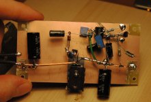
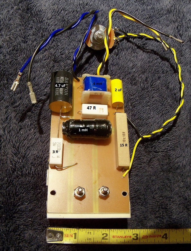
Another board, a modified crossover for the Radio Shack Minimus 7. Note that the blade was not set deep enough so there is a narrow bit of copper left behind but there is still a wide enough gap that it should work fine or it could be scraped away with an exacto knife:
Attachments

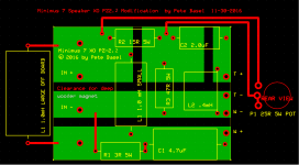
The crossover board a few posts back is for what I am calling the PZ-2.2. Zilch at
Audiokarma asked for Minimus 7 upgrades and I had just spent an afternoon doing
one. He liked it the best, tweaked the values up and down (with my guidance) and
called it the PZ-2.1, I changed one non-critical resistor value and added the option
for a tweeter level control pot and am calling it the PZ-2.2.
Here is the thread at Audiokarma, Zilch took measurements so that's helpful, I
also measured as I did, the initial design but didn't bother to take screen shots:
Minimus 7 Loudspeakers - Measurements | Audiokarma Home Audio Stereo Discussion Forums
Unfortunately many of the pictures seem to be dead links now.
Here is the finished crossover, I forgot to elevate the power resistors. I'll fix that:
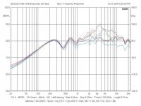
I'm having trouble finding the FR graphs but the one attached shows at the top stock
and the blue and light blue at the bottom are close to this mod, can't find the exact graph,
this graph is one iteration back but close to final.
Audiokarma asked for Minimus 7 upgrades and I had just spent an afternoon doing
one. He liked it the best, tweaked the values up and down (with my guidance) and
called it the PZ-2.1, I changed one non-critical resistor value and added the option
for a tweeter level control pot and am calling it the PZ-2.2.
Here is the thread at Audiokarma, Zilch took measurements so that's helpful, I
also measured as I did, the initial design but didn't bother to take screen shots:
Minimus 7 Loudspeakers - Measurements | Audiokarma Home Audio Stereo Discussion Forums
Unfortunately many of the pictures seem to be dead links now.
Here is the finished crossover, I forgot to elevate the power resistors. I'll fix that:
I'm having trouble finding the FR graphs but the one attached shows at the top stock
and the blue and light blue at the bottom are close to this mod, can't find the exact graph,
this graph is one iteration back but close to final.
Attachments

Last edited:
- Status
- This old topic is closed. If you want to reopen this topic, contact a moderator using the "Report Post" button.
- Home
- Design & Build
- Construction Tips
- Quick Prototype PC Boards - "Etch" by Table Saw