Hello,
I need a little help from someone that knows more about crossover design than I do.") I've got a pair of old vintage Technics speakers that I am in the process of refurbishing. The drivers are still in good shape so my current plan is to reuse them (they are also odd sizes and would be too much trouble to replace with anything available today).
I've got a pair of old vintage Technics speakers that I am in the process of refurbishing. The drivers are still in good shape so my current plan is to reuse them (they are also odd sizes and would be too much trouble to replace with anything available today).
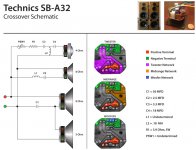
I've got the cabinet improvements done and now I'm trying to design better crossover systems for them. I am completely stumped by the double woofer design. Each speaker has two 10" woofers of different impedances (that appear to be wired in series) in the same airspace. The LP crossover network consists of a single capacitor wired in series on the negative side of the first woofer. Now that I've completely confused you, have a look at the schematic that I've attached.
Can anyone explain this setup? It appears to be breaking several rules of fundamental speaker design.
I need a little help from someone that knows more about crossover design than I do.
I've got a pair of old vintage Technics speakers that I am in the process of refurbishing. The drivers are still in good shape so my current plan is to reuse them (they are also odd sizes and would be too much trouble to replace with anything available today).I've got the cabinet improvements done and now I'm trying to design better crossover systems for them. I am completely stumped by the double woofer design. Each speaker has two 10" woofers of different impedances (that appear to be wired in series) in the same airspace. The LP crossover network consists of a single capacitor wired in series on the negative side of the first woofer. Now that I've completely confused you, have a look at the schematic that I've attached.
Can anyone explain this setup? It appears to be breaking several rules of fundamental speaker design.
Attachments
I thought this looked rather odd so I decided to sim it to see what it did... The answer? As far as spl levels go, nothing, however it does change the blend of the two woofers to achieve the final SPL curve. The really odd thing is that you get the exact same final SPL with or without the cap, or even with a single driver or the two in paralell (the second I understand).
The driver with the cap across it ends up contributing less to the higher frequencies than the 8 ohm driver does.
If I had to hazzard a guess as to what it is doing I would say it is sharing the bass between the two woofers to reduce the overall excursion required to get the same Bass output, whilst having one of them only reproducing the higher midrange. Whether this is helpful or not I'm not quite sure of.
What it definitely does is change the impedance of the drivers, though how this is beneficial or otherwise I'm not sure as there are no other crossover components involved.
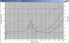
Attached are the impedance plot and SPL plots from the sim.
All I did was take the SPL and impedance curve from my MW144 woofers, adjust one so that it was nominally 8 ohms and a copy so it was nominally 5 ohms. I then made a circuit with the two woofers and the 56uF cap. I also did another with just the two woofers in series.
impedance plot: blue is with just the two drivers in series. Black is with the 56uF cap.
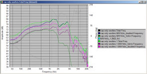
spl plot: Black, turquoise, and bright green all follow the exact same line and only bright green shows on the graph. They are the SPL curves of a the 8 ohm driver alone, two drivers in series, and two drivers in series with the cap.
dark blue and dark green are the contributions of the two drivers with the 56uF cap. Dark Green is the driver with the cap accross it.
Pink and Purple are the two drivers without the cap.
edit: note that this is using two drivers with the exact same SPL but different impedance.... using two drivers with differing spl curves would obviously result in something different.
Tony.
The driver with the cap across it ends up contributing less to the higher frequencies than the 8 ohm driver does.
If I had to hazzard a guess as to what it is doing I would say it is sharing the bass between the two woofers to reduce the overall excursion required to get the same Bass output, whilst having one of them only reproducing the higher midrange. Whether this is helpful or not I'm not quite sure of.
What it definitely does is change the impedance of the drivers, though how this is beneficial or otherwise I'm not sure as there are no other crossover components involved.
Attached are the impedance plot and SPL plots from the sim.
All I did was take the SPL and impedance curve from my MW144 woofers, adjust one so that it was nominally 8 ohms and a copy so it was nominally 5 ohms. I then made a circuit with the two woofers and the 56uF cap. I also did another with just the two woofers in series.
impedance plot: blue is with just the two drivers in series. Black is with the 56uF cap.
spl plot: Black, turquoise, and bright green all follow the exact same line and only bright green shows on the graph. They are the SPL curves of a the 8 ohm driver alone, two drivers in series, and two drivers in series with the cap.
dark blue and dark green are the contributions of the two drivers with the 56uF cap. Dark Green is the driver with the cap accross it.
Pink and Purple are the two drivers without the cap.
edit: note that this is using two drivers with the exact same SPL but different impedance.... using two drivers with differing spl curves would obviously result in something different.
Tony.
Attachments
Thank you so much for doing that! It explains why the low end was so muddy.
My goal is to cross the woofs to the mid at around 700. The 8 and 5 ohm drivers appear to be designed to work together in series, so I'm thinking a sing order LP filter would do it. The combined impedance of the drivers would be 13 ohms -- which would require a 2.9 mh inductor? Do you think this would work or am I over simplifying it?
Thanks again.
Thank you so much for doing that! It explains why the low end was so muddy.
My goal is to cross the woofs to the mid at around 700. The 8 and 5 ohm drivers appear to be designed to work together in series, so I'm thinking a sing order LP filter would do it. The combined impedance of the drivers would be 13 ohms -- which would require a 2.9 mh inductor? Do you think this would work or am I over simplifying it?
Thanks again.
What about the parasitic inductance in the woofers?
Could that have been made larger to avoid the need for an external series inductor?
Hi btnx, I suggest you have a read of the sticky about designing crossovers without measurements http://www.diyaudio.com/forums/mult...designing-crossovers-without-measurement.html yes you are probably oversimplifying it
You could try and see whether you get an improvement of course. Without seeing actual SPL curves for your particular drivers it makes it hard to judge how they will be interacting with the mids. Also you have not determined what value the inductor on the mid is so it is hard to say whether 700Hz is a good crossover point.
Remember that the curves I posted were for MY mids (it was just an experiment to see what effect the 56uF cap had), and your individual bass drivers will have different curves to what I posted.
Tony.
I’m planning on getting response curves & impedance plots from the drivers as soon as I receive a few connections & parts that I have ordered. I know that the curves that you did are not usable for my application but they do provide a general idea of what the filter is doing (and not doing).
I’m trying to learn all that I can from tinkering with these speakers before I attempt to build something more sophisticated. Most likely I will be in over my head very soon and will be back here with more questions.
I’ll read through the crossover design link as well. There looks to be a lot of good information.
Much thanks Tony.
For anybody tinkering with old crossovers, I suggest loading up on a selection of large value film caps from ApexJr. Also ask Steve what inductors he has in stock.
Thanks for the recommendation. You have to love a site that sells a "Bag O' Crossovers".
- Status
- This old topic is closed. If you want to reopen this topic, contact a moderator using the "Report Post" button.
- Home
- Design & Build
- Construction Tips
- Can anyone please explain this design?