Hello.First post. Newbie. Been following the site for a while now.
I was interested on reaching "perfect" grounding in op amp circuits, especially for very low level signals. I am an electrical engineer so i opened all my books, resourced all my sources and generally study the subject again. And i came across this reference from a book i thought (and still think) was a good all -around about op amps.
So...
From Operational amplifiers Winder Clayton fifth edition we read in page 271.
10.4.1 Earth loops
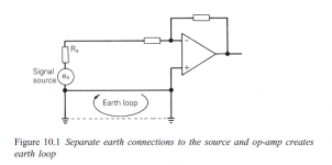
In op-amp applications where both signal source and op-amp are separately
earthed, as shown in , an earth loop is created. (very good so far). The obvious remedy is to earth the system at one point only, usually at the op-amp input. (Whaaa??!!)
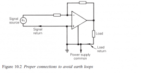
Another earth loop error, which is noticeable when measuring small signals,
occurs when the power supply current or load current is allowed to flow
through the input signal return connection. If this happens, an error voltage
is applied to the input of the op-amp via the signal source; this results in
an error at the output. (again very good so far). The proper connection to avoid this effect is shown in Figure 10.2. The signal return and load return should be connected to power supply common as close to the op-amp pins as possible.
In the second paragraph especially it starts by saying one thing first and afterwards it suggests to do the exact opposite.
Am i missing something?


I don't get 10.2 because it connects V- to ground, which is usually not a very bright idea.
Linear Audio v.5 has an interesting piece on grounding by Bruno Putzeys, which I think is recommendable. The basic idea is that you have to treat signal ground and signal as constituting a balanced pair.
Linear Audio v.5 has an interesting piece on grounding by Bruno Putzeys, which I think is recommendable. The basic idea is that you have to treat signal ground and signal as constituting a balanced pair.
Figure 2 shows apparently a single supply op amp. This drawings are scanned from the book.
I think i know practically and theoretically how to treat real signals, but the thing is that sometimes i begin questioning my self about standard things.
What bothers me most is the obvious lack of practical experience from people writing books about certain subjects and i have seen this repeating quite a lot.
Anyway, i still think the statements an the book are false (fifth edition of the same book), but yet again...
First paragraph seems fine: the way to solve a ground loop is have one and only one ground connection.
The second paragraph is less clear, but makes the valid point that you don't want to inject currents into a signal return.
The trick with grounding is not to follow rules but follow currents: assume all connections are resistors (they are resistors, although small ones).
The second paragraph is less clear, but makes the valid point that you don't want to inject currents into a signal return.
The trick with grounding is not to follow rules but follow currents: assume all connections are resistors (they are resistors, although small ones).
I complete agree that the trick with ground loops is to have one and only connection to common-ground, BUT NOT at the op amp's input as the book says.
Generally talking, let's assume we are dealing with a pcb which contains a number of op amps with their respective sub-circuits. What I would do is connect the ground connections from the IC decoupling capacitors to a named "supply common" which is the common where the voltage regulators connect ,and then connect as close as possible to the reservoir capacitors everything signal named "signal common". Of course this presupposes that no connection is to be made afterwards between supply common and signal common. Someone could go even more fussy about it , but from my personal experience that is good enough.
So what this "how to" tip has to do with connect everything at the op amp's input to avoid ground loops. Ok pcbs are a very mysterious thing, so when someone new to this reads "do that" he'll do and never know what hit him.
Anyway, I 've come to a conclusion that you must first get burned and then find out why you got burned so that you can compare and understand. My advice, trust the application notes.
+1The trick with grounding is not to follow rules but follow currents: assume all connections are resistors (they are resistors, although small ones).
This way there's no rules to remember, it makes sense, and you'll most likely get it right every time.
Following current paths is a rule on its own, and a major one for engineers. You cannot build a system based on a hunch. Connections (and pcb traces and cables) are not just resistors, they are also capacitors, inductors and complex relations between them. Anyway, would anyone do as the book suggests?
http://www.diyaudio.com/forums/diya...udio-component-grounding-interconnection.html
has bibliography - includes web – refs Whitlock's stuff at Jensen Transformers which is great too
has bibliography - includes web – refs Whitlock's stuff at Jensen Transformers which is great too
two books I keep in my reference library which will jump-start everyone on the subject:
Grounding and Shielding Techniques by Ralph Morrison.
And, Noise Reduction Techniques in Electronics Systems by Henry Ott
Thx-RNMarsh
Both Ralph Morrison & Henry W. Ott have written excellent books.
Mr. Morrison has several similar books:
Grounding and Shielding Techniques in Instrumentation
Noise and Other Interfering Signals
Grounding and Shielding in Facilities
But Mr. Morrison is a 'field theory' type of guy, which I struggle with.
********
Mr. Ott's new big book is Electromagnetic Compatibility Engineering.
http://www.diyaudio.com/forums/diya...udio-component-grounding-interconnection.html
has bibliography - includes web – refs Whitlock's stuff at Jensen Transformers which is great too
Has anyone READ this article? More black magic than engineering. But thanks for mentioning it, haven't read it before. Section 4.8 should be first and then all the other sections follow. The author might be right about chassis-safety ground and leakage currents, but there is a lot more in the subject (mainly transformer theory) for NOT doing this. And what about being a noisier environment as you get nearest to the reservoir capacitors than after the regulators. My perception is get "ground 0" then come closer to "ground 0 noise 0". Deep rabbit hole. I might be wrong too.
Also thank you all for your references. I know this is not an engineering forum, and i hope i contribute a little bit to...some things anyway.
http://www.diyaudio.com/forums/diya...udio-component-grounding-interconnection.html
has bibliography - includes web – refs Whitlock's stuff at Jensen Transformers which is great too
Thanks for the link!
- Status
- This old topic is closed. If you want to reopen this topic, contact a moderator using the "Report Post" button.
- Home
- Design & Build
- Construction Tips
- Ground loops