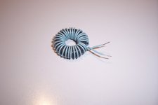
I've found it inconvenient over the years to keep coils around for building crossover prototypes: they're bulky, heavy, and expensive, and I never had the values I needed at hand. Then I discovered the joys of toroidal ferrite inductors for prototyping. Now I keep a modest assortment of cores (sizes FT50, FT82, FT114, and FT140, all type 43), a selection of magnet wire, and this program at hand, and wind them as I need them.
Recently I wanted a pair of 0.56mH coils for small-signal testing. Referring to the program, I found I could make them by winding 33 turns of 23AWG wire onto FT50-43 ferrites. I don't have 23AWG, so I used 24 instead; in minutes I had wound and measured my coils, installed them in the circuit, and begun testing. Altogether I used less than 6' of very cheap wire.
The resistance of these coils is so low that I can't measure it with certainty, but calculating it from AWG specifications gives about 70 milliohms. This got me thinking that coils wound from 32 turns on FT82-43 cores (43" of 18AWG including 3" leads, 23 milliohms) might work as tweeter shunts in my fininshed crossovers, where their miniscule resistance and low leakage would be advantageous.
Obviously, the small amount of wire needed results from the intrinsic efficiency of the toroidal structure and high initial permeability of the ferrite cores; together, these mean that the inductors will saturate at relatively low power. Can somebody tell me how to measure the level at which these coils reach saturation?
Ungapped ferrite is probably the worst choice possible for this kind of application. It saturates very easily, and the initial accuracy is poor, as is the temperature stability.together, these mean that the inductors will saturate at relatively low power. Can somebody tell me how to measure the level at which these coils reach saturation?
In addition, the datasheet of these cores looks like a joke: there is practically no useful engineering data.
Anyway, let's try to work out an example based on the FT50-43.
The formula you have to use is Isat=(Bsat*Ae*N)/L.
Bsat is not given in the datasheet, but from the context I can infer that it has to be a NiZn material; this type of material is good at VHF, but has a poor saturation tolerance; let's say 150mT.
The effective core area isn't given either; it can be approximated from the physical dimensions: ~13.6mm². Number of turns is 33, and inductance 0.56mH.
Thus Isat=(0.15*13.6 10-6*33)/0.56 10-3=0.12A. That is the peak current value at which serious non-linearities will begin to show, that is about 85mA rms. Not very useful for Xover coils
To illustrate the above, here is an example: it shows the behavior of a comparable coil, the current plotted against the volt.second product.
The vertical scale is 100mA/div. The characteristic begins to become visibly non-linear at ~200mA.
Of course, this coil is somewhat different, it is a 250µH one, has a different section, number of turns, and the material is not exactly the same, but it is the same kind of crap.
Ungapped ferrite is good only for suppression coils, transformers, common mode chokes, etc, not for applications where inductance really matters.
It is comparable to Z5U for ceramic capacitors.
Metallic powder cores are much better suited to such applications
Attachments

Wow, thanks, Elvee! I'm very grateful that you took the time to answer me so thoroughly. I'll keep these little buggers on the test bench, and beware their severe limitations. I suspected they'd saturate at low levels, but 1/8 amp? Holy moly!
I filed that formula for future reference. Very cool.
For now I'll stick with my 15-gauge laminated-core tweeter shunts. I'm pretty sure those aren't saturating, and their DCR is quite low already.")
I filed that formula for future reference. Very cool.
These are easily found on eBay, too, so I might play around with them a little. Unfortunately most of them are even more poorly-documented than the ferrites I'm using.Metallic powder cores are much better suited to such applications.
For now I'll stick with my 15-gauge laminated-core tweeter shunts. I'm pretty sure those aren't saturating, and their DCR is quite low already.
A question you might be able to answer . Suppose an ECC 82 or 81 valve might be persuaded to work as a push pull output device with your toroid . It might combine crossover and output to a tweeter . What I have in mind is working at above 7 kHz . Anyone tried this ? My hunch is it will work and will not be impossible to hand wind ? If 7 kHz I would guess 3 kHz TF roll off ( - 3 dB ) . Big transformers seem better one octave above the - 3 dB point .
I recently used a standard wire coil of 0.5 Kg as an inductor . It was fine and a little cheaper than one from Parts Express , in the UK we have nothing like that company at those prices . About $12 , 7 mH and 1R5 DCR which was helpful as I wanted a bit of resistance ( 1 mm if I remember ) .
I recently used a standard wire coil of 0.5 Kg as an inductor . It was fine and a little cheaper than one from Parts Express , in the UK we have nothing like that company at those prices . About $12 , 7 mH and 1R5 DCR which was helpful as I wanted a bit of resistance ( 1 mm if I remember ) .
Last edited:
A question you might be able to answer . Suppose an ECC 82 or 81 valve might be persuaded to work as a push pull output device with your toroid . It might combine crossover and output to a tweeter .
It will not work, at least with ferrite: to get a sufficiently low magnetizing inductance, you will need too few turns to allow for any sizeable power capacity.
With metallic powder toroids, it would be possible
With 10 turns, the v*s product will be extremely small. If you give all the numerical parameters, the power bandwidth can be computed.1 watt would be plenty . No DC in core as PP .
With a loose wind of about 10 windings of 1 mm
I need mainly the effective area of your toroid (cross-section of the ferrite), the intended turns ratio and the output impedance.
Looked at your amp and loved it . Thanks .
The 10 turns was to say already doing something . A similar 6 A choke sold everywhere ( LCR UK and others ) 1.65 mH . Seems a very cheap source of a donor ( $2 ) ?
When I get a moment I will have to build something . Anyone have some starting voltages ? 100 V at 8 mA ( 16 mA total ) ? 2 x LED bias ( red to blue ) . I would not use LED when finished . Could be as long tail pair as the input voltage is not a problem . One side grounded if so .
10 A = OD 30 mm ID 19 mm Thickness 15.33 mm . Thickness was easier to measure . 20 ( 1 mm dia ) turns in fact .
Last edited:
- Status
- This old topic is closed. If you want to reopen this topic, contact a moderator using the "Report Post" button.
- Home
- Design & Build
- Construction Tips
- Toroidal ferrites for prototyping (and more?)