Hi.
I need to start solder small smd parts like TQFP and so on with iron or hot air gun.
I'm gonna place an order at DK for the needed parts like flux and solder.
The solder paste they have is Kester and Chipquik, which is the best?
And also for the flux, Kester or Chipquik?
About the solder removal braid, ther's a thousand of them. What type do I need for small smd parts?
Eventually the price won't be a problem, the quality is mandatory.
Thanks.
Last edited:
Unless you are going to be using an oven or a hot air gun almost exclusively, you don't need solder paste. Just buy the very small solder (0.016"??). It about 31AWG size.
Either of those flux brands should be good. More important is whether you prefer water-soluble, no-clean, highly reactive, etc.
Same with braid. Any name brand ~3mm stuff should work fine.
Either of those flux brands should be good. More important is whether you prefer water-soluble, no-clean, highly reactive, etc.
Same with braid. Any name brand ~3mm stuff should work fine.
Let me tell you to use lead free solder paste. I would regard fine powered lead as an extreme hazard. There are some very nice lead free low melting point solder pastes out there. For example mp. 130C. However pastes don't keep well. I would second the idea of using fine solder wire.
Thank you guys.
At the end, I ordered different types of staff just to see the difference between them.
Seanvn, I wouldn't care much about the lead of the paste since I use a fume extractor. Further, I heard that the lead-free paste/solder joint is not so reliable.
Anyway I'll post images about the outcome of my work (hopefully in a couple of months).
Wish me good luck!
solder paste does not contain powdered lead, it contains balls (spheres) of tin/lead solder. Having worked in this industry and been heavily involved in PCB design fabrictaion and assembly, i have never heard of the lead in tin lead solder being a hazard, and as for the solder paste, even if you snorted it I doubt much would happen, it is combined with tin!!
I have done a lot of work with SMD parts over the years. All of the boards my company produces are SMD, and when I do new designs I make the first few prototypes by hand. The finest pitch parts I have worked with are 025 pitch, which may be a larger pitch than what you are working with, but the principle still holds.
The trick is to use a cheap toaster oven. Don't use the good ones, they heat up too quickly. And, don't use your wife's toaster oven. Find a cheap one at a garage sale or thrift store.
Apply solder paste to the SMD pads using a toothpick or small wire. It takes very little paste to make a good connection. If you apply too much, the solder will just ball up and with fine pitch parts, it will bridge to the adjacent pad.
Place the parts on the board using tweezers doing your best to line things up straight. It is not that critical for most parts, but more so for the fine pitch ones. When the board is heated, the surface tension of the wet solder will help to self-align the parts on the pads. If the fine pitch parts are not aligned well to start, they may self-align one pad off.
Place the board in the center of the oven and turn it on to "Bake" at 200 deg F for 4 minutes. This will bring all the parts up to a low working temperature. If you err on the time, err on a longer soak time at 200 deg.
Raise the temperature setting to 325 deg F for 2 minutes. This will allow the internal temperature to begin to rise without becoming too hot.
Finally raise the temperature setting to 450 deg F. Watch the board carefully. In my oven the solder will start to melt after 45 sec to 1 minute depending on the lead size of the part. Heavy parts with large leads will take longer as their thermal mass in higher. Watch the time closely. From the time the solder melts, leave the oven at 450 for only 30 seconds, then turn off the oven and open the door. This will allow sufficient time for the solder to wet the joint without overheating the part's die.
The boards will be hot, and the solder joints will need time to cool. Let the board sit for 5 to 10 minutes until it is cool enough to handle.
Inspect the board closely using a lighted magnifier if you have one. If there are solder bolls, just pick them off using tweezers or small-nose pliers. They should pop right off. Sometimes an SMD part like a small resistor may ride up on top of the solder, never making a joint. Touch this up with a fine tipped solder iron. On fine pitch parts if tere was too much paste, you may find a solder bridge across tow leads. Use some fine solder wick and a fine-tip iron and the bridge should come off easily.
Good luck!
Last edited:
All good suggestions, and I'll second the toaster oven idea. I double checked the thermal curves for reflow, and I was surprised at the good fit to be honest. I've used a toaster oven, and flux pen on a BGA217 before, successfully.
Also good to use is a paint stripper. Seriously. Get some tinfoil, mould it to shape maybe around a large fitting, so most of the air is vented away from the work and use an AA battery / pencil / pen diameter sized object (10 - 15mm) to pruduce a duct for hot air so you can rework smaller parts.
SyBorg's post is good information, personally, I use a solder paste syringe with a fine nozzle on. Keep the nozzle blocked between jobs with some enameled copper wire of the right size so it doesn't dry out. Lay a fine bead around the chip, and touch up the pins afterwards with a fine iron as SyBorg says. I've used this for 0.4mm pitch TQFP100s before (PIC32MX) as well as DFN / QFN and LGA packages. LGA I'll make a bigger footprint for, so I can touch the iron to it and make sure I can manually reflow after it's been hot aired / ovened on...
And I would recommend lead based paste over lead free - the Xbox red ring of death was apparently due to lead free paste and brittle / poor solder joints.
Just as a final tip, when you've got a board in the oven, make sure you place a blob of paste in all four corners so you can see the temperature has reached melting point all over. Things like SMD inductors tend to take a little longer to reach temperature also, due to the higher thermal mass.
Hope that helps too!
I used a needle point tip in my Weller station and it was OK. Salvation Army never seems to have a cheap toaster oven. Besides, solder paste is really expensive. I have one of those Radio Shack de-solder bulb jobs, but have not found a free aquarium pump for it yet. I also need a used dissecting microscope as I am blind as a bat. I just can't see the board. I keep wondering if those USB micro-cameras will work.
I do a lot of SMD stuff, I make stencils from copper or brass shim stock using toner transfer.
I read through Mooly's thread, I thought I'd just add this...
If you need to remove a SMD part with legs, such as a TQFP, and you don't mind sacrificing the part, and it's rare that there is a real need to salvage them, then cut it off the board using a scalpel or craft knife. You cut the pins one-by-one as close as possible to the chip. You can hear a quiet 'click' when the blade goes through, it should be stopped by a tiny ledge on the package. You have to work very precisely and carefully using both hands on the knife as quite a lot of force is required, you have to be careful that the blade doesn't slip or snap and damage either you or the board.
When you've cut all the legs the chip will drop off if the board is inverted. Then you can pick up all the cut legs with a hot soldering iron and clean the pads with a bit of braid.
The whole process can be very quick.
Ok boys, this is the outcome of my first smd soldering test.
I think it will be all-right.
I realized that the big challenge is the correct alignment of the parts in the pads.
The joints are made with a 2mm scalpel tip and regular 0.7mm Sn/Pb alloy.
After the solder is applied, i used a desolder braid to clean from the excess.
The pictures were taken with a cheap usb camera.
It is an integrated class D amplifier with embedded TI ADC converter and a pic18 mcu.
Last edited:
CC,
Nice job. Looks as good as a commercial board. When you say scalpel tip, is that a scalpe tip modified to be a soldering iron or are you using a chisel tip soldering iron? I am debating which tip to use as I have been using kind of a big 0.035 in chisel lately and it has been tough and not the neatest job.
Nice job. Looks as good as a commercial board. When you say scalpel tip, is that a scalpe tip modified to be a soldering iron or are you using a chisel tip soldering iron? I am debating which tip to use as I have been using kind of a big 0.035 in chisel lately and it has been tough and not the neatest job.
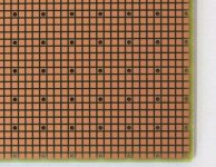
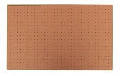
Has anyone used this type of SMD protoboard?
"Grid of 42 mil square pads on 50 mil centers allows SMT components of various sizes and pitches to be mounted."
(I found this one and other types at allelectronics.com)
"Grid of 42 mil square pads on 50 mil centers allows SMT components of various sizes and pitches to be mounted."
(I found this one and other types at allelectronics.com)
Attachments
CC,
Nice job. Looks as good as a commercial board. When you say scalpel tip, is that a scalpe tip modified to be a soldering iron or are you using a chisel tip soldering iron? I am debating which tip to use as I have been using kind of a big 0.035 in chisel lately and it has been tough and not the neatest job.
Hi xrk971.
Sorry for my late reply, I was busy in the last monthts...
I use a Aoyue 968A+ station with a 2mm scalpel tip:
AOYUE SOLDERING,DESOLDERING,HOT AIR REWORK,INFRARED SOLDERING,REPAIRING SYSTEM
the tip is the pn.T-2LD.
This is the method I use to solder smd's:
1 - Place the part in the correct position with the aid of an USB camera. This is the "pain in the a$$" part
2 - While in place, apply solder with the iron on 2-3 pin toghether, no matter if these are shorted.
3 - Repeat step 2 on pins on the opposite side of the IC in order to avoid further component movement.
4 - apply solder on the remaining pins. Don't waste your time trying to avoid shorts, it will be impossible with fine pitch IC's !!!
5 - Remove the excess of solder with a no-clean braid. I found that a 1.27mm large one is OK.
6 - Wash the PCB with a suitable PCB cleaner.
7 - Inspect the joints with the good-old USB camera previoulsy used.
Easy isn'it?

- Status
- This old topic is closed. If you want to reopen this topic, contact a moderator using the "Report Post" button.
- Home
- Design & Build
- Construction Tips
- SMD soldering.