Are you sure its not the old "DC on mains" problem ? although if you are running them at 400va loading then you may be hearing the harmonics as the bridge comes into and out of conduction. Worth looking at though.
Wouldn't like to say on potting compounds. Over the years we had this type of problem on numerous ferrites and HF transformers (TV Trade) and there is so much energy involved that encasing the coils wasn't the success you might have expected.
Wouldn't like to say on potting compounds. Over the years we had this type of problem on numerous ferrites and HF transformers (TV Trade) and there is so much energy involved that encasing the coils wasn't the success you might have expected.
I've got a pair of 500VA transformers that are loaded to 400VA.
They both hum very slightly which can be annoying.
Would I get any benefit from encapsulating them in potting compound ?
Put them in a box that is non magnetic cover with sand and fill with melted paraffin. Potting compound still mechanically couples the noise.
It may just be the way they are.
Another thought, could the VA rating be being exceeded if you have a massive reservoir cap. The charging currents will be huge but the conduction angle relatively small. Could that high peak current be causing saturation ?
I am using 3 x 33000uF per rail. (12 caps in total).
I might try some larger transformers if I can get them in the chassis.
try a DC block. They are relatively inexpensive. Only mod I would make is to add a parallel film cap of the highest value you can find.......point of marginal return would be around 250uf on the film bi-pass caps.

The ESP images have been removed as Rod Elliot specifically asks that any reference to his work be linked directly to his site.
http://sound.westhost.com/articles/xfmr-dc.htm
The ESP images have been removed as Rod Elliot specifically asks that any reference to his work be linked directly to his site.
http://sound.westhost.com/articles/xfmr-dc.htm
Attachments
Last edited by a moderator:
I'll try a DC blocker as suggested, it's easy enough to iron out that possibility.
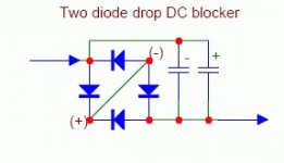
Can anyone tell me why circuit 4 above works. D1 and R2 surely conduct into destruction on the positive half cycle.
Yes it works... the trouble is its been copied out of context and the diode and resistor are part of a worked example explaining the theory.
http://sound.westhost.com/articles/xfmr-dc.htm
Good question and I haven't got the answer. I suppose the question really is what voltage is allowed to develop across the caps. If the reactance is low enough (and hence no or little voltage developed across the cap) then the diodes never come into conduction anyway. Its what happens at the moment of switch on under worst case conditions that counts.
Putting my "practical empirical" head on for a moment I would say that as we usually specify a hefty bridge rectifier for this application (because if you look at the circuit its just a matter of shorting the appropriate connections on the bridge) it becomes a non issue as the surge current of these things is huge. The voltage rating is unimportant as it never sees more than a volt or two.
Putting my "practical empirical" head on for a moment I would say that as we usually specify a hefty bridge rectifier for this application (because if you look at the circuit its just a matter of shorting the appropriate connections on the bridge) it becomes a non issue as the surge current of these things is huge. The voltage rating is unimportant as it never sees more than a volt or two.
1000 VA need a soft start and in particular if those are toroidal transformers.Question:- My 2 x 500VA transformers blow 5A mains fuse on power up. I've had to use a 10A Time Lag. What would the current rating opf the diodes need to be ?
Question:- My 2 x 500VA transformers blow 5A mains fuse on power up. I've had to use a 10A Time Lag. What would the current rating opf the diodes need to be ?
extract below says if you do not use a soft start device (like an NTC inrush limiter) diode current requirements go up. I was surprised to see the 25A and 35A rectifier recomendation. IMO, It's much cheaper to use an NTC inrush limiter and the smaller diodes.
--------------------------------extract---------------------------------
The circuit shown above satisfies all criteria. There is more than enough capacitance, and the diodes specified have a continuous current rating of 3A and a peak current rating of 200A (non-repetitive). After this circuit is included, the no-load current falls back to 16mA, and the visible signs of asymmetrical saturation are gone. As transformer load increases, the diodes will take over from the caps, preventing the peak voltage across either capacitor from exceeding 1.3V - even during the inrush current period.
Note that if no soft-start circuit is used, larger diodes are highly recommended. Regardless of whether soft-start is used, a 25A or 35A bridge rectifier assembly is a simple and relatively inexpensive way to obtain very high current diodes, already neatly packaged and insulated. When using a bridge, remember that + and - must be shorted together to obtain 4 diodes in anti-parallel (as shown in Figure 3).
------------------------end of extract -----------------------------------
- Status
- This old topic is closed. If you want to reopen this topic, contact a moderator using the "Report Post" button.
- Home
- Design & Build
- Construction Tips
- Humming Transformers