Hi, firstly I apologise for being so thick! I am trying to experiment with dac chips. I am using this site
DAC Final
as a guide for construction techniques :just to learn. I want to use this guy's technique of using DIP switches to set , high or low, the control pins for the WM1870 (and other dac chips for that matter)
http://www.wolfsonmicro.com/documents/uploads/data_sheets/en/WM8740.pdf
The fellow goes into a lot of detail here but I cannot for the life of me figure out how to wire the switch to the 5v rail / the ground/ and the dac. I realise I could just solder the pins to 5v rail or ground rail directly but at the end of the day I am still clueless as to how to use the DIP technique also the switch would allow very easy A and B listening to try various filters on and off...Can any body help explain? I am going to use a single 8740 in stereo mode so I take it pin 6 is left floating instead of connected to 5v when used in mono mode. Thanks Alan
Look at the datasheet, page 5. Some inputs have internal pull-up resistors, some pull-down. If these inputs are left floating (unconnected) then those inputs with internal pull-UP resistors default to logic 1 - hence connect a DIP switch to this input to the GND connection. Conversely, those inputs with an internal pull-DOWN resistor connected default to logic 0 if left floating, hence connect a DIP switch to the positive going rail (DVDD).
Pin 6: DIFFHW. Internal pull-down, activated by pulling high to DVDD for 'MONO' mode (i.e. if using 2 of these ICs). Hence yes, leave it floating for your application. Data sheet not too clear on this really.
Andy
Pin 6: DIFFHW. Internal pull-down, activated by pulling high to DVDD for 'MONO' mode (i.e. if using 2 of these ICs). Hence yes, leave it floating for your application. Data sheet not too clear on this really.
Andy

Again I apologise for being so thick! I am really struggling with this. The site says "if you see the dip switch ON then connect to ground: otherwise to 5v". The circuit diagram of the switch is confusing me. There are no resistors because dac has them. So do you connect all the pins to the side of the switch closest to the dac to 5v and solder the pins of the other side of the switch to "ground" so when the switch says "on" the pins go to earth/ground? BUT!!!! Surely then you would just send 5 volts into the ground plane ie making the ground a power rail?
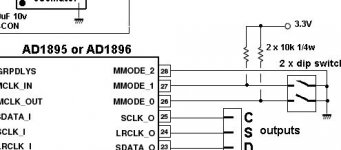
If I look at the ad1896 example its different here. The power rail actually passes through a resistor when the switch is "on" and a power rail can go to ground through a series resistor, just as say Salas suggests to do to test one of his power regs..
So surely what the guy on the site really means is that with the wolfson
pin 23 : switch off then pin connected to nothing
switch on then pin connected to 5v!! indeed : not earth
pin 24 : always to groundie not switched
pin 25/26/27/28: switch off then pins to nothing
switch on then pins to ground
Or am I completely wide of the mark?Like I said sorry for being so thick.
Attachments
Correct. Some are connected to DVDD, some connected to GND.There are no resistors because dac has them.
NO!!... because:So do you connect all the pins to the side of the switch closest to the dac to 5v and solder the pins of the other side of the switch to "ground" so when the switch says "on" the pins go to earth/ground?
BTW, 'ground' IS a power rail.BUT!!!! Surely then you would just send 5 volts into the ground plane ie making the ground a power rail?
Connect the DIP switch as stated in my first post. Connect the logic input pin to one side of a DIP switch. The other side of the DIP switch is connected to either DVDD or GND (to DVDD if the input has a pull-down resistor, to GND if the input has a pull-up resistor).
SO, this is what happens to a pin that has an internal pull-DOWN resistor:
Dip switch to input pin, other side to DVDD (+5V).
-Dip switch OPEN (off): the internal resistor pulls the voltage level to LOGIC1
-Dip switch CLOSED (on): the DIP switch pulls the voltage level to LOGIC0
*If input put left 'floating' (no DIP switch connected, or DIP switch is OPEN or off) then the pin will be at LOGIC0
SO, this is what happens to a pin that has an internal pull-UP resistor:
Dip switch to input pin, other side to GND (0V).
-Dip switch OPEN (off): the internal resistor pulls the voltage level to LOGIC0
-Dip switch CLOSED (on): the DIP switch pulls the voltage level to LOGIC1
*If input put left 'floating' (no DIP switch connected, or DIP switch is OPEN or off) then the pin will be at LOGIC1
Does that now make sense???
Andy
almost makes sense
surely an input pin with a pull up resistor already has an " internal " voltage to it? That is why the dip switch goes to Ground. With the voltage to it we get LOGIC 0.
Shut the switch, pass the voltage to gnd: LOGIC 1....So if the pin floats its the same as an open (off) dip switch so logic would be at LOGIC 0
Andy if its getting too hard I understand you giving up. I have however learnt enough to rig a switch up properly and I think I will get the answer emperically. I was going to make a big mistake because I did not realise the relationship of pull up resistor/switch/gnd and pull down resistor/switch/5v All dacs use this system to set logic....I think you saved me smoking the chip and my brain cells....I just followed how the dac is set in the photo and its just opened up a whole series of more questions but I will get the answers to these myself once its all soldered up....many thanks
YES! Hurragh! We got there in the end!with a pull up resistor when the switch is open the logic pin is held high
so you could say that the default of such a pin is high ie logic 1. A closed switch sets the pin low , changes the default setting.

...and the opposite is true for an input that has a pull-DOWN resistor.
A
PS
Your self-detected error mentioned above when trying to understand DIP switches and their application to an input pin would not have resulted in damage to the chip - YES you would have shorted the supply rails by connecting DVDD +5V to GND when the DIP switch was closed - this may however resulted in damage to the power supply
Sh1t! I think I got it ar$e about face above! I'm sure I re-read before posting. Try again:
SO, this is what happens to a pin that has an internal pull-DOWN resistor:
Dip switch to input pin, other side to DVDD (+5V).
-Dip switch OPEN (off): the internal resistor pulls the voltage level DOWN to LOGIC0
-Dip switch CLOSED (on): the DIP switch pulls the voltage level to DVDD LOGIC1
*If input put left 'floating' (no DIP switch connected, or DIP switch is OPEN or off) then the pin will be at LOGIC0
SO, this is what happens to a pin that has an internal pull-UP resistor:
Dip switch to input pin, other side to GND (0V).
-Dip switch OPEN (off): the internal resistor pulls the voltage level UP to LOGIC1
-Dip switch CLOSED (on): the DIP switch pulls the voltage level to LOGIC0
*If input put left 'floating' (no DIP switch connected, or DIP switch is OPEN or off) then the pin will be at LOGIC1
Oops! Sorry about that, girlfriend was prancing about the living room half naked last night and was ever so slightly distracting me - hehe
hahah no problem I could see the mistake but I said nothing because I did not want to be a smart **** ...so yes it really has sunk in.I really glad you helped me there. Thanks Andy... So I have just cooked up a etched pcb for the dac with dips and going to add the dips to the ad1896 tomorrow SOoooo hopefully...Further the Italian guy has made a mistake by saying "see the switch on :go to ground.See the switch off :go to 5v"...he forgot that pin 23 is a pull down!!.. My latest mistake! I put the wrong side of transparent image of the circuit board over the photoboard so I got a mirror image ( still populated the board tho )!!!!!!
Again thanks loads, learnt something at last!
Again thanks loads, learnt something at last!
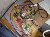
Theres no schematic , I did it copying the Italian guys site. I put the cs8416 and AD 1896 on the same board and wired point to point. This will make dac changing easy, I want to try and rig up a a/b/c/d/ testing dac so I can change by the click of a switch.I believe this is the only way to truely test things.
I had a Cs4397 chip but smoked it . I gave every power pin in that dac its own transformer winding and reg. OVERKILL but the sound was nuts..Never heard anything that comes close but that statement means nothing as I have no access to bona fide HIGH END KIT...All I know is that I was very very happy and amazed by it and the memory of that is my marker.
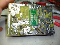
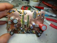
So I have done the same thing here to all but a few pins. I have lost count of the regs...but its very complicated. So to ease the build I had a go at a pcb and just made it up as I went along on the free version of EAGLE....I messed up putting the wrong side of the image face up , so had to invert the chip so it works on the board but this is good because I can solder bypass caps almost dead on to the pins now! I used an adapter board for the wolfson because I have has trouble with the etchant dissolving the tiny pin traces so gave up.
The 5v regs are LT1021 given steroids with pnp 2n2905 transistors. I suspect this ruins the regs superb noise rejection but I know they are cheap and sound superb.any 3.3volt pins have the lt1021 then a ams3.3 reg thats the best I can do or know how to.
The grounding I never fully understand. My present conception is that we have digital and analogue. They should be separate.They should meet in a castleated shape.The ground is noisy before a reg:quiet after. So I put the quiet analogue and digital ground under the chip and linked it to the copper on the other side of the board by numerous vias. And having just read about the castleated thing just this minute cut a castled trace out so its a bit rough looking.I did not dare try and make a double sided board with eagle incase I messed up. It was my only board . The quiet grounds of all the chips in the dac will go to the star ground of a tubed pre amp.
The tubed pre amp was a tubed output for the cs4397. But I have read the wolfson has a very strong output so need no output stage. So by moving a few caps and a couple of volume pots I the output stage is now a pre amp.
I hope it works . I still have not put the dip on the ad yet. Had enough for today...If you got any tips or critism Andy feel free to say because I am clueless to what I am doing I just have a go..
I had a Cs4397 chip but smoked it . I gave every power pin in that dac its own transformer winding and reg. OVERKILL but the sound was nuts..Never heard anything that comes close but that statement means nothing as I have no access to bona fide HIGH END KIT...All I know is that I was very very happy and amazed by it and the memory of that is my marker.
So I have done the same thing here to all but a few pins. I have lost count of the regs...but its very complicated. So to ease the build I had a go at a pcb and just made it up as I went along on the free version of EAGLE....I messed up putting the wrong side of the image face up , so had to invert the chip so it works on the board but this is good because I can solder bypass caps almost dead on to the pins now! I used an adapter board for the wolfson because I have has trouble with the etchant dissolving the tiny pin traces so gave up.
The 5v regs are LT1021 given steroids with pnp 2n2905 transistors. I suspect this ruins the regs superb noise rejection but I know they are cheap and sound superb.any 3.3volt pins have the lt1021 then a ams3.3 reg thats the best I can do or know how to.
The grounding I never fully understand. My present conception is that we have digital and analogue. They should be separate.They should meet in a castleated shape.The ground is noisy before a reg:quiet after. So I put the quiet analogue and digital ground under the chip and linked it to the copper on the other side of the board by numerous vias. And having just read about the castleated thing just this minute cut a castled trace out so its a bit rough looking.I did not dare try and make a double sided board with eagle incase I messed up. It was my only board . The quiet grounds of all the chips in the dac will go to the star ground of a tubed pre amp.
The tubed pre amp was a tubed output for the cs4397. But I have read the wolfson has a very strong output so need no output stage. So by moving a few caps and a couple of volume pots I the output stage is now a pre amp.
I hope it works . I still have not put the dip on the ad yet. Had enough for today...If you got any tips or critism Andy feel free to say because I am clueless to what I am doing I just have a go..
Attachments
- Status
- This old topic is closed. If you want to reopen this topic, contact a moderator using the "Report Post" button.
- Home
- Design & Build
- Construction Tips
- dip switch on pins 28 to 23 :wm8740 dac