I've done a bit of searching and everything I've found relates to attenuating a signal that will be further processed after the drop, but all I need to do is reduce input before the signal hits the meters, from an independent output dedicated to them (accessory output from my DAC) so quality after attenuation isn't crucial for me.
I've built a passive switcher in the past, couldn't I just figure out how much resistance I would need, and then add the resistors in series at each corresponding position before the meters?
If so, would all the positions be joined at the meters' +/- end, so the attenuated values used would be determined by the switch?
Thanks for your reply, and sorry for not being clear. Yes, they're mechanical VU's and they've got built in rectifiers and cards (not sure what the cards are called but they've got the necessary resistors to work with signal). I've tested them and have been able to get "0VU" from a 1kHz signal from my system.
What I'd love to do is create an attenuation circuit for the meters to display different (attenuated) values, like "0" (for full signal) and then "-6" (figure out how much resistance I need for this) and so on.
I was hoping to be able to accomplish this by having the input signal go into a rotary switch with maybe 3-4 positions, and adding the necessary resistors at each position, then feed the meters with the signals and determine what signal moves them via the switch, hope that makes sense!
Where there are a lot of unknowns then it might be simplest to just use a potentiometer (or preset) to determine the values needed. Then measure the value and fit a fixed resistor/s
There are a lot of unknowns... such as what voltage do the meters need to show 0DB. What is input impedance of the meter, and so on.
With a rotary switch you could use 4 preset pots and set them exactly how you want.
There are a lot of unknowns... such as what voltage do the meters need to show 0DB. What is input impedance of the meter, and so on.
With a rotary switch you could use 4 preset pots and set them exactly how you want.
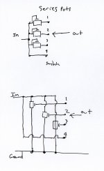
Just to add... the presets can be wired in series (possibly... it depends on the meter. If the meters have on board powered electronics then series connected may not be the best solution) or better still wired as a true divider with the output taken from the wiper and the ends of the pot grounded.
Can you see how that would be wired to the switch. Four presets in parallel with the wipers going to the four poles of the switch and the meter to the switch "output".
Can you see how that would be wired to the switch. Four presets in parallel with the wipers going to the four poles of the switch and the meter to the switch "output".
Thanks Mooly, great info! I think I understand what you're saying. If I understand this right, I would split the input signal (from my interface, it's 0.775v = 0dBu) into four, each one having a preset pot attenuated accordingly, going into a position on the switch (one wouldn't have one as it would be the "0" position) and then use the poles on the switch as an output to the meters. Hopefully I've understood this correctly, thanks again!
Yes, that's it. The value of the pots depends on the meter sensitivity (its resistance)
If you use the lower example remember that the pots are all in parallel and so a load on the DAC output.
Another scheme is to construct a single divider chain with 4 resistors whose tappings then go off to the switch. That's the hardest one to do but the most elegant")
If you use the lower example remember that the pots are all in parallel and so a load on the DAC output.
Another scheme is to construct a single divider chain with 4 resistors whose tappings then go off to the switch. That's the hardest one to do but the most elegant
Attachments
- Status
- This old topic is closed. If you want to reopen this topic, contact a moderator using the "Report Post" button.
- Home
- Design & Build
- Construction Tips
- Input Attenuation to feed meters (switch?)