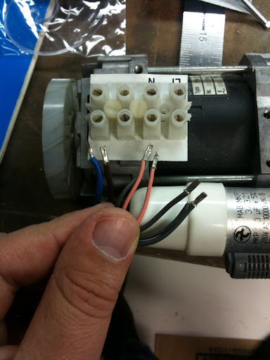
I got my hands on a KNF pump for my DIY RCM based on the Loricraft. The pump has the same specs as the Loricraft KNF, but the wiring looks a little different and has me a little confused. I called KNF and talked to a nice guy who got in touch with Germany and found the wiring schematic, but the colors are off. There is a black and a red together, a black(thick) and black together, and a single red and single black(thick). There are 2 thick black wires and 2 thin. The capacitor is pretty easy to figure out.
Any help would be great.
Any help would be great.
I don't know whats confusing..you..forget the colours and check the components with a meter then look at the colours to give you a guide ")
You need to use a multimeter and find the two windings..first with ohms range.. then mark the wires(start and end) for winding 1 and 2..
The supply goes through the cap to the winding so find the cap..it will charge up on the meter and the ohms will climb to open circuit reverse it the same happens.. Then find the two windings that is a good start you may be able to link the colours to the diagram.
If the conection between the winding and the cap is inside the motor then you will read the aux winding and cap series resistance that will climb to infinity..
Regards
M. Gregg
Last edited:
This is close to what you appear to have,
Single Phase Induction Motor Control Theory | Circuit Diagram
You don't seem to have a start switch just an over temperature switch or CB..connecting the live L1 to the circuit..
The 2nd diagram is what you have (no switch)
Regards
M. Gregg
Single Phase Induction Motor Control Theory | Circuit Diagram
You don't seem to have a start switch just an over temperature switch or CB..connecting the live L1 to the circuit..
The 2nd diagram is what you have (no switch)
Regards
M. Gregg
Last edited:
Thank you so much for your reply here is what I came up with. The capacitor is on the outside and is directly wired so it's separate and easy to deduce. I used my mm and this what I got.
Red Blk- 166.2
Red B/B- 166.2
Red R/B- 115.6
Blk B/B- 0.0
Blk R/B- 50.7
B/B R/B- 50.6
I'm sorry, but this still has me confused. I do understand The Circuit diagram you linked and that makes tons of sense, but can you help me correlate the two. Thanks again for your help.
Red Blk- 166.2
Red B/B- 166.2
Red R/B- 115.6
Blk B/B- 0.0
Blk R/B- 50.7
B/B R/B- 50.6
I'm sorry, but this still has me confused. I do understand The Circuit diagram you linked and that makes tons of sense, but can you help me correlate the two. Thanks again for your help.
Here is how to approach it..
Find your (Can't make out) if its an over temp or CB switch.. it will be short circuit..IE a closed switch find and connect that first from L1... then connect the cap to the correct connections.. then see how many connections you have left..
At a guess (it might not be)..the reversable winding may be single ends ie not connected to anything else,,
So get to this point first.. Could this be your switch/cb? Blk B/B- 0.0
The 166.2 is interesting at a guess these are the windings and the two connections on there own are the reversable winding
(Its difficult at a distance to do this so its at your own risk)
You could contact the guy who gave you the diagram and ask him to get the values of the windings..that would confirm it..
You only have 6 connections (I see you holding) so:
2 for each winding +4
2 for the CB/over temp..
Regards
M. Gregg
Last edited:
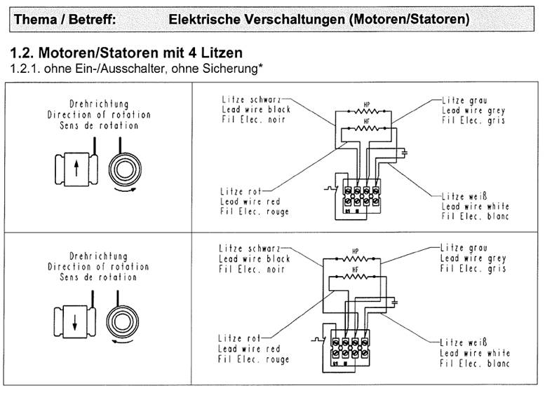
I have stared at this for a while and reread everything. B/B and blk can't be a switch because that would leave me with red and r/b being my only wires left. The switch in my estimation is auxillary. B/B, Red, Black, and R/B would have to be HP and HF. 1.2 Motor/Stator with 4 strands 1.2.1 Without on-/off switch without backing up. If what I'm saying sounds like hogwash please feel free to let me know. I appreciate your help.
I don't think B/B and blk are a switch because that would leave me with red and R/B. I believe the switch is auxillary. B/B,R/B,Red, and Black have to equal HF and HP in my estimation.
1.2. Motor/Stator with 4 strands.
1.2.1. Without on-/off switch, without backing up.
If this sounds like hogwash feel free to let me know. I appreciate your help.
sorry for the double post didn't realize the moderator needed review
1.2. Motor/Stator with 4 strands.
1.2.1. Without on-/off switch, without backing up.
If this sounds like hogwash feel free to let me know. I appreciate your help.
sorry for the double post didn't realize the moderator needed review
Last edited:
What you say sounds reasonable,
I guess the wires connected togeather may give a clue..
Can you get any more information regards windings resistance from manufacturer?
This would be a way to ensure no mistakes are made..
If you can't get any more info I guess you are going to have to go for best guess...
Regards
M. Gregg
I guess the wires connected togeather may give a clue..
Can you get any more information regards windings resistance from manufacturer?
This would be a way to ensure no mistakes are made..
If you can't get any more info I guess you are going to have to go for best guess...
Regards
M. Gregg
This is the only way that makes sense..
As I say its at your own risk..
However black to red&black dosen't tie?? <<<<all the other tests do..
you may be able to break it down further..
115
Red////////////Red&Black
50
Black&Black///////////Red&Black
Black(single)<<<connected to Black and Black<<<just a connection
///////////=winding
Regards
M. Gregg
Last edited:
Looking at the results..
At your own risk..
At this point we don't know which value could be which winding??
You need to some how confirm that 115 is auxilary if you connect it up could you ask someone with this pump to tell you what DC readings they get across each of the terminals on the strip? and check before power up..
We have to assume that 115 could be the auxilary winding..one being 50 the other 115?
This might hold true IF we think:
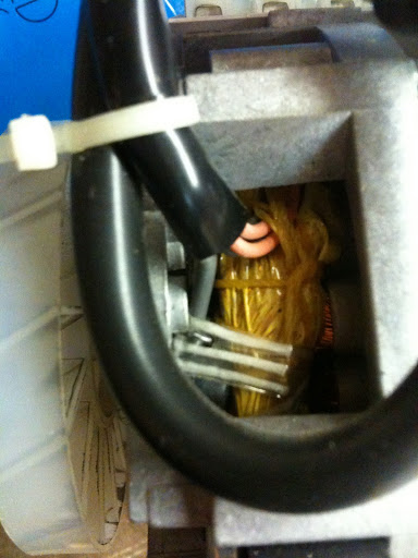
The single black with 0 ohms...could there be a thermal trip inside the motor?
If there is then the black could be L1 if we follow to the connection B/B what winding does that give us??
Remember this is all possible maybes
This may not be any help until you can prove the values of the windings..and these are only my thoughts..I can only base ideas on what you have posted
Regards
M. Gregg
At your own risk..
At this point we don't know which value could be which winding??
You need to some how confirm that 115 is auxilary if you connect it up could you ask someone with this pump to tell you what DC readings they get across each of the terminals on the strip? and check before power up..
We have to assume that 115 could be the auxilary winding..one being 50 the other 115?
This might hold true IF we think:
The single black with 0 ohms...could there be a thermal trip inside the motor?
If there is then the black could be L1 if we follow to the connection B/B what winding does that give us??
Remember this is all possible maybes
This may not be any help until you can prove the values of the windings..and these are only my thoughts..I can only base ideas on what you have posted
Regards
M. Gregg
Last edited:
The bottom line is,
Until you get more information from supplier...I would not power up..
You also don't say what current this motor is supposed to draw..
It only looks small so I would think low current..
If 115 is not the aux then how would that fit to the digram that you have?
Regards
M. Gregg
Until you get more information from supplier...I would not power up..
You also don't say what current this motor is supposed to draw..
It only looks small so I would think low current..
If 115 is not the aux then how would that fit to the digram that you have?
Regards
M. Gregg
Last edited:
Final comment,
I measured the primary of a 6VA mains Tx value over 300 ohms 240V..
I don't know what voltage its running on so...
If you have no choice and no other input from guys that have one of these pumps..You could put a mains lamp in series at initial start. Measure the current..
So if I was to ignore the diagram for a minute then:
High value run winding
With low value aux winding in series with a cap..
Regards
M. Gregg
- Status
- This old topic is closed. If you want to reopen this topic, contact a moderator using the "Report Post" button.
- Home
- Design & Build
- Construction Tips
- RCM vacuum pump help.