Folks, what is your experience in diy electronics without pcb? Seems it would provide better conductivity because design with fewer soldering points is possible. With PCB signal travels from component's lead to solder to copper trace to another component's lead. Without one it's only one soldering and leads physically touch.
Anyone with personal experience to share?
Anyone with personal experience to share?
in my mind you will not win in sound quality without using PCB you may win in less resistance, less heat and so on, but i would still use a PCB to get neat and compact board.
i personally hate the 3 dimensional mazes. i'm always afraid something will short or just break.
trick to minimize losses with a PCB is in the design of the board.. first compact and LOGICAL placement of parts and also the use of good boards. there are different copper thicknesses available, use a ticker copper board and tin the board after development. for leads that transfer more current you can always solder on more material, a copper wire for example or i have used some old solder wicks for wider tracks.
also it really helps to use silver solder, a lot more conductive then usual solder. and i'd say it is easier to solder also.
but that's just me.
also it really helps to use silver solder, a lot more conductive then usual solder. and i'd say it is easier to solder also.
Wow that is just so wrong.
If you can measure any significant difference in resistance between joints made with different types of solder then the problem is not with the solder, but rather with the joint you made.
High silver content solders are used in specialized applications where the materials involved do not work well with the standard tin based products. For standard electronics normal solder is more than sufficient. If anything, the higher general melting points of silver bearing solder increases the chance of making a bad joint.
In any case, most new solder formulations contain some silver (2-4%) not because of any direct benefit of silver, but rather as part of a usable alloy to replace the use of lead.
-bill
)
PCB based amps
I was old schooled and passed a NSA soldering test for space flight electronics. 60/40 used...
PCB's have advantages and disadvantages, anything created proper will work, not done right will just not perform as desired. I prefer PCB with wide traces and wide spaces. You must watch component location and adjacent traces for cross feed, capacitance coupling. I keep heater supplies off of the PCB and use twisted pair, must be over 1/2" off of the PCB.
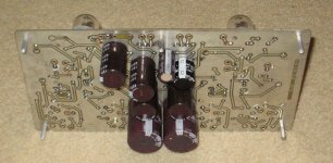
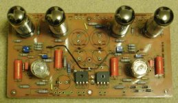
I also like maximum ground plane with stitching to keep any ground plane current from developing a potential that could result in feedback / ground loops. This PCB was designed to fit on an 8.5x11 sheet to allow for toner transfer PCB fabrication.
You can make amps as quiet as a church mouse until you crank them up!
This PCB is a prototype suggested by KEGGER. It can use 6P3S Russian 6L6 tubes all the way to KT88's etc... I played with different tubes and component values to look for sensitivity and flexability. After months of different combinations, GNFB, no GNFB, UL, Triode, PIO, metalized poly, etc... I preferred 6550's Triode connected with older Hammond 6.6k 40 watt iron@ 450VB+
It was a very pleasant amp with low end authority at 350V B+ with the 6P3S tubes which would have been the lowest cost version.
I was old schooled and passed a NSA soldering test for space flight electronics. 60/40 used...
PCB's have advantages and disadvantages, anything created proper will work, not done right will just not perform as desired. I prefer PCB with wide traces and wide spaces. You must watch component location and adjacent traces for cross feed, capacitance coupling. I keep heater supplies off of the PCB and use twisted pair, must be over 1/2" off of the PCB.
I also like maximum ground plane with stitching to keep any ground plane current from developing a potential that could result in feedback / ground loops. This PCB was designed to fit on an 8.5x11 sheet to allow for toner transfer PCB fabrication.
You can make amps as quiet as a church mouse until you crank them up!
This PCB is a prototype suggested by KEGGER. It can use 6P3S Russian 6L6 tubes all the way to KT88's etc... I played with different tubes and component values to look for sensitivity and flexability. After months of different combinations, GNFB, no GNFB, UL, Triode, PIO, metalized poly, etc... I preferred 6550's Triode connected with older Hammond 6.6k 40 watt iron@ 450VB+
It was a very pleasant amp with low end authority at 350V B+ with the 6P3S tubes which would have been the lowest cost version.
Attachments
Roline, you have some of the best toner transfer results I have seen.
Some info about your setup would be good too - printer, paper,
toner, laminator (or whatever you use to transfer), number
of passes and so on would be very helpful.
I had mixed results till recently. I just realized that the clothes iron I have
at its max setting was too hot and I got better results at
a lower temperature.
The most correct answer is "it depends". I have build direct wire chassis, wire wrap, vector boards, and etched boards. I pick what is needed at the time, how complex the design is and how impatient I am. For an op-amp or complex circuit, yea double side boards, but I have a dead-bug mic preamp that is clean to -130 dB. I worked on things in the lab that were perfect in a breadboard and never worked when we made the boards as the parastatics are different. On the flip, I worked problems where we could only fix it by controlling the impedance issues on a etched board. A great example was the original HBO receivers where half of the circuit was actually the etch.
An oft overlooked method is to dead-bug on a copper clad board, using the un-etched plane as a ground plane, and direct wire 30Ga between legs of everything parmabonded to the board. Sounds like a kludge, but you can get a very quiet circuit.
I too passed certification in the 60/40 through-hole days.
f anything, the higher general melting points of silver bearing solder increases the chance of making a bad joint.
In fact , silver in soldering alloys reduces melting point. Ordinary Sn60/Pb40 has melting point of 188 degrees C, but Sn62/Pb 36/Ag2 is 178 C.
Similar effect is in lead free alloys,silver bearing types have the lowest melting point.
In fact , silver in soldering alloys reduces melting point. Ordinary Sn60/Pb40 has melting point of 188 degrees C, but Sn62/Pb 36/Ag2 is 178 C.
Similar effect is in lead free alloys,silver bearing types have the lowest melting point.
Just 10 degrees difference ain't that much. Silver containing tin/lead solder (so non-ROHS) has a higher mechanical strength than plan 60/40 tin/lead solder which is why it is used in specific cases. I haven't read of (nor experienced) any difference in conductivity. Besides that, when you bent the lead wires of components the lead wire will make contact with the copper PCB track and the solder is mostly for curing the electrical joint i.e. keeping it in place mechanically. The best way for good connections AFAIK but so old fashioned some wish to disagree on that as it is forgotten technique.
So bend the wire 45 degrees then use your pliers and cut it to the length you wish and then solder the joint. Often people solder and then cut the wire which gives mechanical stress on the joint which will shorten its lifespan/reliability.
That being said: I almost never use silver solder while I have a roll of Siltech and some stuff from other brands. I get the best joints with plain lead containing Fluitin. Good stuff, especially the variant that contains a few % copper.
Last edited:
Often people solder and then cut the wire which gives mechanical stress on the joint which will shorten its lifespan/reliability.
Thi is only a problem ifyou cut through the solder as well as the wire.
I always cut just above the soldered joint.
NO ! I heard this so many times. When you use standard pliers you will always put some force on the joint while cutting it. This is a fact not some story. That is why special pliers are made for electronics by Knipex etc. Standard pliers have an angle in which they cut and while cutting they will pull the wire up which is force in my book. I use special Knipex cutters and the angle they cut has been optimized for putting the least stress on the joint as possible but still...
If it is not the pliers it will be your hands putting some force on the wire/joint when cutting. This can easily be avoided by doing it the other way around which costs nothing in terms of money or time. Just think different and try it out. Joints also look better when they're cut first and the surface that was cut will be tinned too which leaves not a chance for corrosion of the otherwise bare copper. Only this should be reason enough for "cutting first".
In military stuff the rule is : "first cut then solder"....
Last edited:
NO ! I heard this so many times. When you use standard pliers you will always put some force on the joint while cutting it.
In military stuff the rule is : "first cut then solder"....
I always use light side cutters, pliers are a bit heavy and liable to put a lot of stress on the joint. Cant say I have had any problems in 30 years of soldering with broken joints.
Category "I drink and drive for 30 years and never had an accident" ") I can tell joints will break down earlier on power electronics etc. where hefty currents flow through solder joints but don't take my word for it and simply try it out once. I realize myself that longevity is a rare item in modern society so maybe debating the subject is pointless. The device will end up in the bin before the joints will break. Still I hope airplanes are built according these old fashioned standards.
I can tell joints will break down earlier on power electronics etc. where hefty currents flow through solder joints but don't take my word for it and simply try it out once. I realize myself that longevity is a rare item in modern society so maybe debating the subject is pointless. The device will end up in the bin before the joints will break. Still I hope airplanes are built according these old fashioned standards.
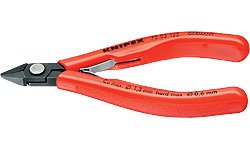
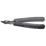
It is quite possible I used the wrong words in english to name a tool as english is not the language I use everyday. I meant these of course:
I can tell joints will break down earlier on power electronics etc. where hefty currents flow through solder joints but don't take my word for it and simply try it out once. I realize myself that longevity is a rare item in modern society so maybe debating the subject is pointless. The device will end up in the bin before the joints will break. Still I hope airplanes are built according these old fashioned standards.It is quite possible I used the wrong words in english to name a tool as english is not the language I use everyday. I meant these of course:
Attachments
Last edited:
That is why special pliers are made for electronics by Knipex etc.
In military stuff the rule is : "first cut then solder"....
I think this is advertising propaganda originated by Knipex or some other tool manufacturer, or more likely an old wives tale (not uncommon in the military).
Think about the difficulty of developing data on the subject. You'd have to have failure mode analysis data developed from identical products, some cut before and some cut after soldering, all identified as to which was which.
I worked in a Racal (now Vodafone) factory producing military radios. We produced many thru-hole PCBs hand-stuffed on manual pick-and-place machines. The leads were all automatically trimmed on a machine after soldering.
As far as PCBs are concerned, the big advantage of a computer-produced PCB is the low likelihood of connectivity issues if the schematic is correctly drawn and the repeatability. The more complex the design, the greater the probability of error in point-to-point wiring and on perfboard.
Last edited:
I think this is advertising propaganda originated by Knipex or some other tool manufacturer, or more likely an old wives tale (not uncommon in the military).
ard.
I was trained to the DEF2000 standard and we were never told to cut first.
I think this is advertising propaganda originated by Knipex or some other tool manufacturer, or more likely an old wives tale (not uncommon in the military).
Think about the difficulty of developing data on the subject. You'd have to have failure mode analysis data developed from identical products, some cut before and some cut after soldering, all identified as to which was which.
It is sometimes difficult to accept a different truth. It is simple: when you don't apply mechanical force at all chances are likely that the joint will live longer. Same kind of truth like: you don't need to clean stuff if you don't make it dirty etc.
I worked in a Racal (now Vodafone) factory producing military radios. We produced many thru-hole PCBs hand-stuffed on manual pick-and-place machines. The leads were all automatically trimmed on a machine after soldering.
They were trimmed and not cut I guess ? AFAIK this is done with high speed rotary cutters (for a reason).
Last edited:
- Status
- This old topic is closed. If you want to reopen this topic, contact a moderator using the "Report Post" button.
- Home
- Design & Build
- Construction Tips
- To PCB or not to PCB?