Cal Weldon Consulting at it's finest.
If that was a free sample, the paid service must be unbelievable!

The long pin is the positive and the shorter is the negative. If you have a multimeter you can also test it with the mode to test resistance, if a material has a lower resistance than xxxOhm(200 with my decive) it wil 'beep'. So when the LED lights up you can see from you probes wich is positive and negative(COM=negative). The multimeter will send a little current trough the led to test resistance but this will also let you LED work.
The long pin is the positive and the shorter is the negative. If you have a multimeter you can also test it with the mode to test resistance, if a material has a lower resistance than xxxOhm(200 with my decive) it wil 'beep'. So when the LED lights up you can see from you probes wich is positive and negative(COM=negative). The multimeter will send a little current trough the led to test resistance but this will also let you LED work.
May or may not work depending on the band gap voltage of the LED, typically a few volts, vs the voltage from the multimeter, typically in millivolts.
Looking at the LED is an old trick... many new ones don't conform nowadays.
It's never a problem, a DVM on diode check lights most to confirm, if it doesn't a 9 volt battery and 10 k resistor does.
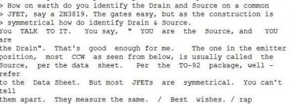
And just to go slightly off topic, where it does get really spooky is identifying the drain and source on a common JFET.
I have the "official" answer from the man himself (Bob Pease of National Semiconductor) if anyones interested")
It's never a problem, a DVM on diode check lights most to confirm, if it doesn't a 9 volt battery and 10 k resistor does.
And just to go slightly off topic, where it does get really spooky is identifying the drain and source on a common JFET.
I have the "official" answer from the man himself (Bob Pease of National Semiconductor) if anyones interested
May or may not work depending on the band gap voltage of the LED, typically a few volts, vs the voltage from the multimeter, typically in millivolts.
Worked perfectly for my 7-segment displays. It won't work with high brightness LED's I think. He can only try to know it
Hi all
Unfortunately the old trick of checking the lower wire with the chip attached might not be a reliable guide - some LEDS have anode substrate others cathode substrate.
Many LEDS are not able to handle high reverse voltages. Even a 9V battery used in many digital meters might be too high (according to the data sheet).
The forward voltage of a LED might be too high for measuring the resistances on an old meter with 1.5V battery (and Avo's 15 V for high resistance may cause more damage).
Simplest way is to hook up a 4.5V battery through a 220 ohm resistor and see which way it lights.
Cheers
John
another big theme thread 
diode test on every DVM will tell what positive and what negative is , and you don't even need to know what these things called cathode and anode are
in proper way connected - led will shine enough and you'll see up to 2000mV voltage drop on meter
anyway - I didn't meant that OP's question is dumb or naive ; same thing I asked myself zillion times , but I never was able to remember answer gained by using DVM ....
Last edited:
Pease uses a battery and resistor, FWIW.
Think we have covered all possibilites for testing LED polarity so here's the JFET way.
He talks to them... honest
Not sure it would work for LED's though.
Attachments
A good multimeter (Fluke) will be able to test diodes/leds in this mode. I think it will deliver less than 9volts trough your components, so if you test a led for a few seconds it won't blow.
most of them (DVMs) will deliver as much they can from installed battery , pumping 1mA through DUT
Thanks everyone for your input. I of course knew how to use a DVM and battery to test the LED polarity. The reason I asked if you could tell from simply looking is that I was at work pulling a night shift at the hospital in my call room and I had my PCB, the LEDs and a soldering iron.... no DVM or battery & resistor with me and 6 hrs until the shift was over. I wanted to get these LEDs soldered b/c I was bored but was at a loss on telling the polarity without my tool box. I decided to wait until I got home in the end, tested them with the DVM and FWIW these particular LEDs have a long lead on the small internal anode so....I could have used the advice above, both the lead length test and the internal structure test were both correct in this case.
Thanks,
Jeff
Thanks,
Jeff
- Status
- This old topic is closed. If you want to reopen this topic, contact a moderator using the "Report Post" button.
- Home
- Design & Build
- Construction Tips
- LED polarity