Hi guys,
I wonder if you could please advise a complete newbie. I used to be a telecomms engineer but I have never studied electronics. I can use a soldering iron, not brilliantly but I tend to get by.
Now this may make you laugh")
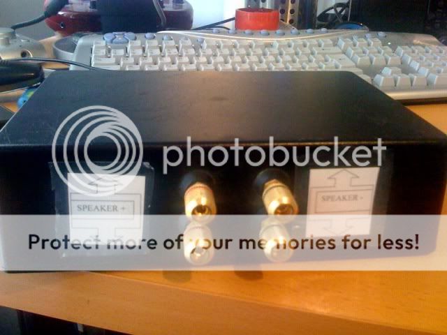
I built some external crossovers for my Mission 751 Speakers about 12 years ago after reading about something similar in Hi-Fi World.
I sent off one of my crossovers to Russ Andrews and they suggested the parts I needed and then I built a couple of box's. In all it cost me around £200 to do which was a lot of money for me then. I didn't really know what I was doing but just copied the originals.
They seemed to work ok, up to a certain volume and then the amp would cut out via a protection saftey cut out in the amp I suppose
I thought I would bring the 751's back into service but I want to sort out the box's first. I have recently decided to take a look at them and think I have worked out what goes where, etc
I have a couple of questions if someone can help???
1.
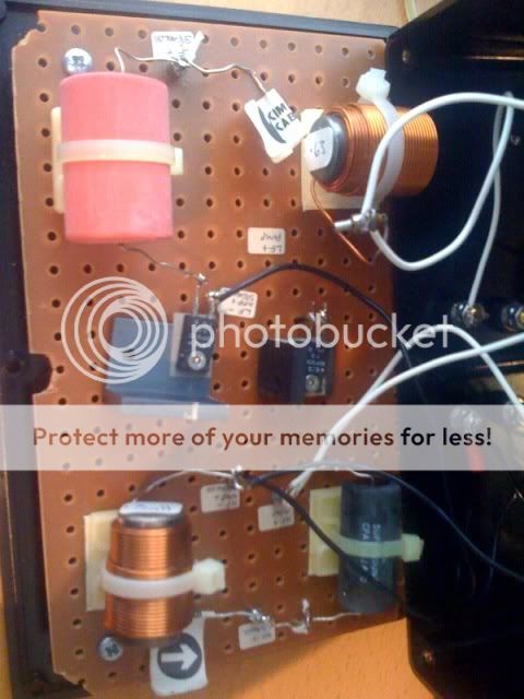
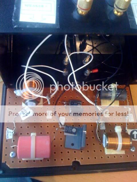
I had two metal film resistors attached to the same heat sink for both the LF and HF with a grey strip, in one box I had attached them to the top of the resistor in the other box I had placed it under the resistor between the heat sink.
I have cut the two heat sinks in two now in both box's so that they have their own heat sink.
Do the grey strips go between the resistor and heat sink or on top of the resistor?
You might think I have made a complete dogs dinner of this but it was my first try
2.
The speakers are supposed to be 6 Ohms, what is the best way for me to measure them with my multimeter?
3. Single or bi-wired?
I am thinking if not bothering with biwiring them as I think that it doesn't really make any difference, and is more of a marketing ploy to sell more cable. What's the general opinion?
Thanks
Lee
I wonder if you could please advise a complete newbie. I used to be a telecomms engineer but I have never studied electronics. I can use a soldering iron, not brilliantly but I tend to get by.
Now this may make you laugh
I built some external crossovers for my Mission 751 Speakers about 12 years ago after reading about something similar in Hi-Fi World.
An externally hosted image should be here but it was not working when we last tested it.
An externally hosted image should be here but it was not working when we last tested it.
I sent off one of my crossovers to Russ Andrews and they suggested the parts I needed and then I built a couple of box's. In all it cost me around £200 to do which was a lot of money for me then. I didn't really know what I was doing but just copied the originals.
They seemed to work ok, up to a certain volume and then the amp would cut out via a protection saftey cut out in the amp I suppose
I thought I would bring the 751's back into service but I want to sort out the box's first. I have recently decided to take a look at them and think I have worked out what goes where, etc
I have a couple of questions if someone can help???
1.
I had two metal film resistors attached to the same heat sink for both the LF and HF with a grey strip, in one box I had attached them to the top of the resistor in the other box I had placed it under the resistor between the heat sink.
I have cut the two heat sinks in two now in both box's so that they have their own heat sink.
Do the grey strips go between the resistor and heat sink or on top of the resistor?
An externally hosted image should be here but it was not working when we last tested it.
An externally hosted image should be here but it was not working when we last tested it.
An externally hosted image should be here but it was not working when we last tested it.
You might think I have made a complete dogs dinner of this but it was my first try
2.
The speakers are supposed to be 6 Ohms, what is the best way for me to measure them with my multimeter?
3. Single or bi-wired?
I am thinking if not bothering with biwiring them as I think that it doesn't really make any difference, and is more of a marketing ploy to sell more cable. What's the general opinion?
Thanks
Lee
The grey strip,
U don't need them. These are bad conductors of electricity, but good conductor of heat.
But if the sil-pads are omitted you'd have to use thermal compound instead to ensure good transfer of heat to the sink.
U will only use them if two components having electrical connection on their metal body are mounted on a common heatsink.
Or if the mounted component has a voltage on its case and the heatsink is in contact with a different voltage (ie if the heatsink is earthed).
It's best practice for the heatsink to be earthed and insulated from the component. If the heatsink is left "floating" it will act as an aerial and pick up noise which will then couple to the circuitry through stray capacitance. I don't know if this is such a big deal with the large signal levels and low impedances in a loudspeaker circuit though.
The DC resistance of the speakers can be measured with a multimeter, just disconnect anything else they're in parallel with first. The nominal impedance is usually the average over the frequency range, don't panic if the measured resistance is lower. Speaker impedance rises at higher freq's as the voice coil's inductance becomes significant WRT the coil's resistance. It is also greater at the speaker's resonant frequency; the magnitude and frequency of this peak are both affected by the size of the speaker box.
I know nothing about bi-wiring beyond reading a very brief description years ago which led me to believe it was not worth the trouble. But a search on this forum will likely provide you with as much info as you'd like, if not more.
Measuring DC resistance of the speaker (either just drive units or the complete unit) doesn't tell you much as Omega_Void eludes. Mine (B&W 703) are 8 ohm nominal, but dip to 3 ohms... and that's the manufacturers figures... how can you call that 8 ohm
It's easy to measure and plot impedance but you need a scope and signal generator to do it.
It's easy to measure and plot impedance but you need a scope and signal generator to do it.
Measuring DC resistance of the speaker (either just drive units or the complete unit) doesn't tell you much as Omega_Void eludes. Mine (B&W 703) are 8 ohm nominal, but dip to 3 ohms... and that's the manufacturers figures... how can you call that 8 ohm
"eludes"... eh? I think you mean "implies". I actually said the measured DC resistance would be lower than nominal. I elaborated on why, but didn't actually claim the reactances were measurable with a multimeter.
It's easy to measure and plot impedance but you need a scope and signal generator to do it.
Or if your PC has a soundcard you can download ARTA and use the LIMP utility to measure. Works in the program's demo mode, so it's free. The necessary connections are cheap and easy to make, especially if the soundcard has headphones output.
"eludes"... eh? I think you mean "implies". I actually said the measured DC resistance would be lower than nominal. I elaborated on why, but didn't actually claim the reactances were measurable with a multimeter.
Lol... it's early morning, cup of tea in one paw, poking keyboard with the other
Implies, hints at even.... I even got your name wrong, put gmphadte's there instead but managed a quick edit before the system clocked it Oh that's okay, Omega_Void isn't my real name anywayI even got your name wrong
- Status
- This old topic is closed. If you want to reopen this topic, contact a moderator using the "Report Post" button.
- Home
- Design & Build
- Construction Tips
- help, metal film resistor and heatsink?