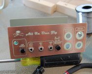
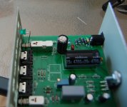
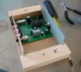
Here are detailed instructions for assembly of the speaker testing jig designed HERE.
Please let me finish posting all of the instructions before you contribute or ask a question.
First step is to un-pack the parts. The kit comes with all of the parts inside the enclosure so you will need to loosen the screws to open it. It is not necessary to completely remove the screws. Be careful when removing the cover not to force it and damage either the enclosure or the front panel. The slots that the front and back panel sit in leave very little wood at the edge and this is easily broken. Should you decide to paint or otherwise finish the box, now is the time to do it.
This pic shows the parts and some of the tools needed to assemble the kit:
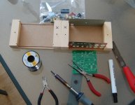
The "X" on each side of the case show where they line up, just make sure the x on each half are together before screwing the case together again (unfortunately, I didn't do this on the first lot that went out).
Soldering iron, cutters, pliers, solder and I like to use flux on all the pads before I solder them as it makes for a trouble free joint.
A file can be helpful to "fine tune" something but I didn't find I needed it at all here.
Next sort out the resistors and the diodes:
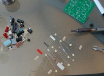
The resistors are not marked and it is best to measure them with a multimeter anyway before installing them. The diodes are fairly easy, the larger ones are rectifiers and the smaller ones are zeners. Be careful of the polarity when you are putting them in.
After you have the resistors and diodes in, the board will look like this:
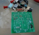
Next go ahead and put in the ceramic caps (2) and the smaller electrolytics.
Please let me finish posting all of the instructions before you contribute or ask a question.
First step is to un-pack the parts. The kit comes with all of the parts inside the enclosure so you will need to loosen the screws to open it. It is not necessary to completely remove the screws. Be careful when removing the cover not to force it and damage either the enclosure or the front panel. The slots that the front and back panel sit in leave very little wood at the edge and this is easily broken. Should you decide to paint or otherwise finish the box, now is the time to do it.
This pic shows the parts and some of the tools needed to assemble the kit:

The "X" on each side of the case show where they line up, just make sure the x on each half are together before screwing the case together again (unfortunately, I didn't do this on the first lot that went out).
Soldering iron, cutters, pliers, solder and I like to use flux on all the pads before I solder them as it makes for a trouble free joint.
A file can be helpful to "fine tune" something but I didn't find I needed it at all here.
Next sort out the resistors and the diodes:

The resistors are not marked and it is best to measure them with a multimeter anyway before installing them. The diodes are fairly easy, the larger ones are rectifiers and the smaller ones are zeners. Be careful of the polarity when you are putting them in.
After you have the resistors and diodes in, the board will look like this:

Next go ahead and put in the ceramic caps (2) and the smaller electrolytics.
I made a couple of mistakes on these boards. The first is that the holes for the mini jacks are a bit big but it is only an issue on the middle one (it uses the internal switch of the jack). As shown in the pic it needs special attention to solder this one:
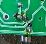
Before the boards went out, I scraped some of the soldermask off of the trace to provide some pad area for soldering. Make sure that solder bridges the trace on both sides of the pin. It can be a bit tricky but is doable.
Install the rest of the jacks, including the power jack.
Next you will need some silicone or other type of adhesive to hold the big cap in place:
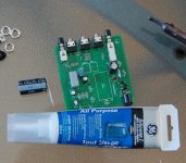
Bend the leads on the cap (careful to watch polarity) and put some adhesive on the side that faces down. Solder in the cap and take a break while the adhesive cures.
Once that is dry move to the chipamp. Here we see my second mistake: the chipamp needs a washer between it and the back plate. A small aluminum washer (not supplied) would be best but since the amp doesn't put out much power, it never get much more than warm so any kind of metal washer will do. Heatsink compound is not needed here:
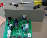
The back panel is predrilled for the bolt (not supplied) and notched for the power jack. These should line up well but if not, adjust the notch with a metal file.

Before the boards went out, I scraped some of the soldermask off of the trace to provide some pad area for soldering. Make sure that solder bridges the trace on both sides of the pin. It can be a bit tricky but is doable.
Install the rest of the jacks, including the power jack.
Next you will need some silicone or other type of adhesive to hold the big cap in place:

Bend the leads on the cap (careful to watch polarity) and put some adhesive on the side that faces down. Solder in the cap and take a break while the adhesive cures.
Once that is dry move to the chipamp. Here we see my second mistake: the chipamp needs a washer between it and the back plate. A small aluminum washer (not supplied) would be best but since the amp doesn't put out much power, it never get much more than warm so any kind of metal washer will do. Heatsink compound is not needed here:

The back panel is predrilled for the bolt (not supplied) and notched for the power jack. These should line up well but if not, adjust the notch with a metal file.
Last edited:
Next put the banana jacks in the front panel and wire them up:
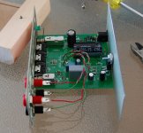
I didn't mark the polarity on the board for these but common is toward the rear. BP 1,2 goes to banana jacks marked "Amp Out To Speaker" while BP 3,4 goes to "Impedance Measure".
Supplied in the kit is a rubber bumper that needs to go on the bottom of the enclosure, under the power jack. It supports the board in this area:
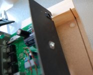
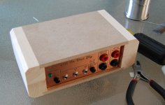
Put the cover on and check the fit. It should go on easily and close tightly at the seams:

I didn't mark the polarity on the board for these but common is toward the rear. BP 1,2 goes to banana jacks marked "Amp Out To Speaker" while BP 3,4 goes to "Impedance Measure".
Supplied in the kit is a rubber bumper that needs to go on the bottom of the enclosure, under the power jack. It supports the board in this area:

Put the cover on and check the fit. It should go on easily and close tightly at the seams:

Next is to double check your work, look for solder bridges and loose leads. Check the polarity on all of the components again.
It is time to try it. Connect a suitable AC power adapter (12-24VAC, 1 amp) and turn it on. On first turning it on, it will have some DC at the output but this drops after a few seconds (with a speaker connected, it will give a little "pop" and hum for a few second. This hum is normal and will cease - output to the speaker at that time should be dead silent).
Once you have verified that it's not on fire D) connect it to your soundcard and give it a test drive:
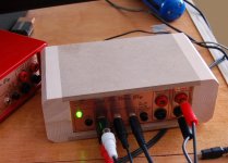
It is now ready for action!

It is time to try it. Connect a suitable AC power adapter (12-24VAC, 1 amp) and turn it on. On first turning it on, it will have some DC at the output but this drops after a few seconds (with a speaker connected, it will give a little "pop" and hum for a few second. This hum is normal and will cease - output to the speaker at that time should be dead silent).
Once you have verified that it's not on fire

It is now ready for action!
Here is the BOM. I didn't think it was of much use as the PCB has all of the values printed on it.
View attachment AIO_BOM.pdf
Updated Schematic:
View attachment AIO_SCH.pdf
View attachment AIO_BOM.pdf
Updated Schematic:
View attachment AIO_SCH.pdf
Last edited:
For example: R10 is 2.7K or 6.8K?
Hi Ed,
I did make some minor changes without updating the schematic but the correct values are printed on the board.
R13 on the BOM is listed as 10ohms, it is three 30ohm resistors in parallel.
Last edited:
Hi,
Could you post one closeup/medium-hires picture of the assembled board so that we (who don't remember resistor color band coding) can go by your picture to place the appropriate resistors in their correct spots? I can somewhat see from the picture you already posted, but some are not quite clear...
Thanks!
Hi critofur,
Like I said here:
It is always a good idea to actually measure the resistors before placing them. I do this on everything I make.
I'll post a pic a bit latter. I don't have one on file.
Like I said here:
The resistors are not marked and it is best to measure them with a multimeter anyway before installing them.
It is always a good idea to actually measure the resistors before placing them. I do this on everything I make.
I'll post a pic a bit latter. I don't have one on file.
I had misplaced my meter, found it now I'm good to go... I'll measure, like you recommend.
Cool - the 30s are 30.0 Guess my meter is only good to three digits. Shows how much I know about DMMs... The 1K shows 1.000 K.
The 68K measures 67.8 - is there any need to make note of that value - I'm guessing it's not used in a position that will affect calibration (but I don't know, didn't go through the circuit diagram to see what that one is doing).
Cool - the 30s are 30.0
The 68K measures 67.8 - is there any need to make note of that value - I'm guessing it's not used in a position that will affect calibration (but I don't know, didn't go through the circuit diagram to see what that one is doing).
Last edited:
I assumed that's why you used three, and that they are used as the 10.0 Ohm resistor used both for calibration, and, for impedance measurements - is it not used for impedance?The three 30 ohm resistors paralleled should give a very accurate 10 ohms - this exact value is needed for later calibration.
Is the other triplet done for increased power handling?
Ok, I've finished building the board, all that's left is to paint the case...
I just realized - all my power supplies are DC. The recent technology switching power supplies (much lighter "wall warts") - do you think those come in AC?
Any suggestions on which power supply choices would be good / good value?
Hope to try this sucker soon.
Thanks,
Chris
EDIT: How about this? http://cgi.ebay.com/ws/eBayISAPI.dll?ViewItem&item=200416808189
...Connect a suitable AC power adapter (12-24VAC, 1 amp) and turn it on..
I just realized - all my power supplies are DC. The recent technology switching power supplies (much lighter "wall warts") - do you think those come in AC?
Any suggestions on which power supply choices would be good / good value?
Hope to try this sucker soon.
Thanks,
Chris
EDIT: How about this? http://cgi.ebay.com/ws/eBayISAPI.dll?ViewItem&item=200416808189
Last edited:
I assumed that's why you used three, and that they are used as the 10.0 Ohm resistor used both for calibration, and, for impedance measurements - is it not used for impedance?
The paralleled 30 ohm resistors make up the internal "known" load of the jig.
I'll go through calibration for Speaker Workshop (to measure driver impedance and other specs) in a new thread that I'll start soon.
I just realized - all my power supplies are DC. The recent technology switching power supplies (much lighter "wall warts") - do you think those come in AC?
Any suggestions on which power supply choices would be good / good value?
EDIT: How about this? HP C4557-60004 AC ADAPTER +18V 1.7A WARRANTY 30 DAYS - eBay (item 200416808189 end time Mar-10-10 16:43:33 PST)
The adapter you linked to is not AC output either.
The one I used is this one: AC to AC adapter 12VAC, 1Amp
I made a mistake earlier when I said 12-24VAC, it should be 12 to 16VAC, 1 amp. The power supply smoothing cap is rated to 25V. The jig operates perfectly on 12VAC at 1 amp and that is the voltage I recommend.
Hmm, that one doesn't come with a plug, but this one does:
An externally hosted image should be here but it was not working when we last tested it.
- Status
- This old topic is closed. If you want to reopen this topic, contact a moderator using the "Report Post" button.
- Home
- Design & Build
- Construction Tips
- Speaker Testing Jig Assembly Thread
