Hi Cristi,
I am building a six channel HT amplifier that uses 6x LM3886 modules. Each modules has 3x LM3886 in parallel and the local reserve is 6600uF per rail (13200uF total per modules) @ +/-36Vdc.
I am using your SMPS2000R PSU. Connecting the first three modules and powering worked extremely well then when adding a fourth module I was starting to get Over Corrent led flash for 2-3 sec then the PSU would kick in no problem. Adding the fifth module worked as well but it was 5-6 seconds of OC but on my last module, the OC light keeps on flashing and PSU does not start. If I turn off the mains power for 3-4 seconds and power back on it start working properly without any issues.
Do you know what could be done to help with this issue?
Thanks
Do
Seems that you experience the phenomenon described in posts #580 and #577. http://www.diyaudio.com/forums/conn...-mode-power-supplies-smps-12.html#post3350326
Your amplifier seems to have a larger total capacitance than can be charged in the very first moments of soft-start sequence. to make things worse, the amplifier also draw a considerable current and discharge the caps till the next start-up try.
there are few sollutions:
first you should try to keep all the amps muted during start sequence and realease the mute after 2-3 seconds when the voltage had settled to nominal value, to decrease a little the quiescent current. of course this method does not deal with the burden of excessive capacitane.
another method, less elegant would be to add an additional soft start circuit, at the output of the power supply, not on the mains side, on each rail. this can be made of two large power resistors, 3-8R and at least 25W, connected in series with the power supply and amplifier and each shorted by a relay once the voltage has reached the nominal value.
Third method, the most elegant but not suggested at all because involves intervention on the power supply, is to increase the soft start ramp time. I would not detail, as it requires extreme care and detailed knowledge and because of dangerous mains voltages present on the board.
You can also try to decrease the capacitance by replacing the stock capacitors of the amplifier board with better ones, and less capacitance. I have no idea what capacitors were used, but I'm almost sure wasn't Panasonic FC's on that boards. you can use 1000uF high quality ones instead of stock caps. being powered from a regulated SMPS so much capacitance won't make things better, expecially if they are cheap (or even refurbished) caps.
please try to activate the Mute function during start-up, this will decrease a bit the quiescent current. to do that, probably you just have to increase the cap connected at pin 8 of each LM3886 for longer Mute time. this depends on the board design of course.
A slow charge circuit using a series string of NTC Power Thermistors with a relay bypass, should allow a susceptible protected SMPS to start up.................... this method does not deal with the burden of excessive capacitane.
another method, less elegant would be to add an additional soft start circuit, at the output of the power supply, not on the mains side, on each rail. .............
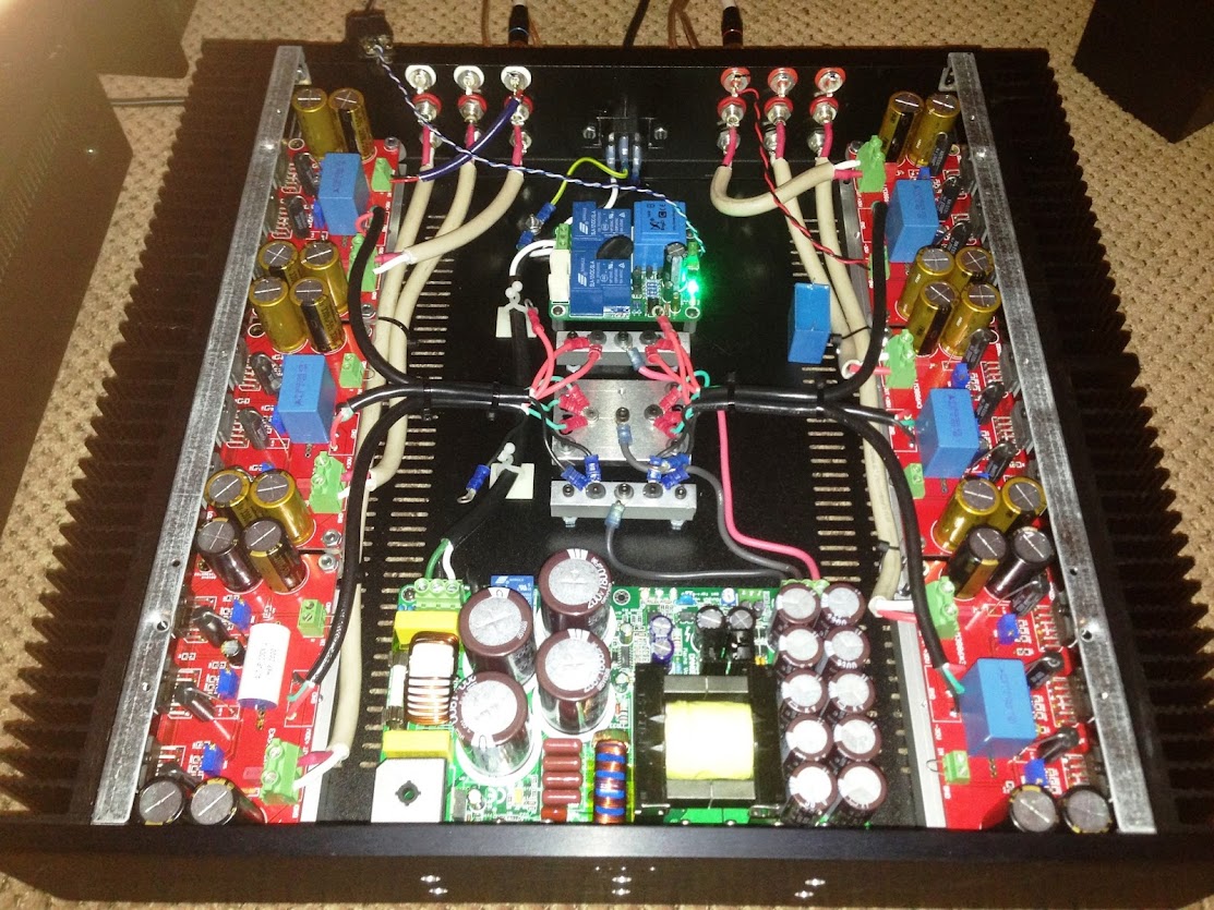
To give you an idea of the setup (this is an older pictures)
I might try to reduce all caps to 1500uF instead of 3300uF which is a faster alternative and if the sound is not good then I will add a softstart.
All modules were built by myself and I only chose good components, so everything new from reliable sources like Mouser or Digikey, etc...
Thanks
Do
I might try to reduce all caps to 1500uF instead of 3300uF which is a faster alternative and if the sound is not good then I will add a softstart.
All modules were built by myself and I only chose good components, so everything new from reliable sources like Mouser or Digikey, etc...
Thanks
Do
Last edited:
Some progress and good news as well ???
I have decided to keep all my local Nichicon on the amp modules and to remove all caps from the second bank on the SMPS (10x 3300uF) and replace them with 10x Pana FCs 220uF.
This should work fine since the SMPS is able to charge the 52800uF on four amps plus his own secondary bank of 33000uF. They total 85800uF in total.
If I power 6 amp modules I will have 79200uF + 2200uF from the SMPS which will equal to 81400uF. It should be good.
Let me know if you have any doubts
Thanks
Do
If my idea is good to use, would it be better I use Caps with lower ESR or lower Impedance on the second bank of the SMPS2000R?
Nichicon Lower Impedance
Pana FC lower ESR
Thx
Do
Nichicon Lower Impedance
Pana FC lower ESR
Thx
Do
The amplifier decoupling is used to supply the short term transient currents.
The smoothing capacitance is quite effectively isolated from these transients by the impedance of the wiring between the main capacitors and the amplifier devices that actually allow current to flow to the load.
The smoothing capacitance is quite effectively isolated from these transients by the impedance of the wiring between the main capacitors and the amplifier devices that actually allow current to flow to the load.
I can't design, nor evaluate, an SMPS, so I can't offer an unbiased opinion on SMPS.
I can design linear Transformer+rectifier supplies and linear + linear regulation.
Here I do not believe that the main supply to the output devices should be regulated. A simple linear is good enough, but it MUST be able to deliver current without the voltage collapsing.
I can design linear Transformer+rectifier supplies and linear + linear regulation.
Here I do not believe that the main supply to the output devices should be regulated. A simple linear is good enough, but it MUST be able to deliver current without the voltage collapsing.
I can't design, nor evaluate, an SMPS, so I can't offer an unbiased opinion on SMPS.
I can design linear Transformer+rectifier supplies and linear + linear regulation.
Here I do not believe that the main supply to the output devices should be regulated. A simple linear is good enough, but it MUST be able to deliver current without the voltage collapsing.
Yeah, I totally understand but it was just the space requirement needed for linear PSU for powering 6 of those amps boards that caused an issue. But it does sound really good for its purpose which is Home Theater.
Ciao!
Do
Hi Cristi
I bought two of your A1000SMPS power supplies a couple of years ago to use with a pair of SDS-254 Class D Audio amp boards. I have finally gotten around to starting to build the amps up and I realize that the power supplies have no heat sink nor heat slug attached. I know at the time you communicated that the switches and diodes should be thermally coupled to the base of my aluminum case for the amp. The base of the case will be 1/8" (3mm) aluminium plate to which I will couple the diodes/switches using the insulation tabs and screws provided. My questions are:
1) Should I use thermal paste on either side of the insulation tabs?
2) What size should I make the 3mm aluminium base plate for effective heat control?
The base plate will mount to 75mm tall extruded aluminium sides and a 3mm aluminium top plate. Alternatively I could mount the power supply to its own 3mm aluminium plate and mount this with thermal paste to the base plate of the amp enclosure.
Any advice you can offer would be greatly appreciated.
Best regards,
Dave.
3 mil base plate is a bit thin to conduct the heat away from the supply quickly. I would use a 8mm plate to make the thermal connection, or use an L shaped alu piece to connect to the case thermally. An Alu case most likely will be sufficient to cool the supply in domestic use.
flyboi, please resend the mail,
Eric:
the rated power or smps must be chosed in such way that the smps will be able to deliver at least the total power of the amplifiers. in your case, 1200W the next suitable smps is just SMPS2000R for the moment. later this year a smaller version will be available probalby 1200W which will close the gap between 800W and 2000W of R series smps.
Any update on a SMPS between the 800 and 2000 ? 1200W would be great for my application.
Thanks!
Hello Cristi et al,
I am a happy owner of some Connex SMPS. One of them, a SMPS800R, is embedded on the back of a sub.
Unfortunately, the SMPS is noisy when the sub is playing. The frame of the SMPS transformer is lose and vibrates loudly.
Is there any solution to consolidate the frame and wire ? with some kind of glue maybe ?
Any advise is welcome,
thanks
Al
Al, please use a 2 components epoxy which can settle in less than one hour to secure the core of the transformer. A loose core can create some annoying noise but the electrical parameters of the transformer won't be changed significantly if any, as long as the core is not broken, and the magnetic path not interrupted.
I wrote a more complete answer to your mail couple of days ago but I always get that error with message not delivered from "Mail Delivery Subsystem"...
Do, please contact me by mail for details regarding SMPS modification.
I wrote a more complete answer to your mail couple of days ago but I always get that error with message not delivered from "Mail Delivery Subsystem"...
Do, please contact me by mail for details regarding SMPS modification.
- Status
- This old topic is closed. If you want to reopen this topic, contact a moderator using the "Report Post" button.
- Home
- More Vendors...
- Connexelectronic
- Switched Mode Power Supplies (SMPS)