Cristi,
I'm interested to buy a SMPS2000R to power a 6 channel amplifier. Each modules is a LM3886 x 3 in parallel capable of delivering 150W.
So I guess the right supply is the SMPS2000R. If I choose custom voltage, say 38Vdc, does it support +/- 10% voltage adjustment as well?
Thanks
Do
I'm interested to buy a SMPS2000R to power a 6 channel amplifier. Each modules is a LM3886 x 3 in parallel capable of delivering 150W.
So I guess the right supply is the SMPS2000R. If I choose custom voltage, say 38Vdc, does it support +/- 10% voltage adjustment as well?
Thanks
Do
Bernie, the voltage is variable, output load and temperature dependendent. when the temperature rise, the fan speed rise too, and the speed is higher for the same temperature when the output current demand is higher.
Dominic, I got your order and we spokt by mail in the meantime,
Dominic, I got your order and we spokt by mail in the meantime,
Hi Cristi,
I am using your SMPS800R power supply with an SDS-470 amp board from Class D Audio.
It generally works great, except, I noticed that when I turn it off, there's a "thud" or "thump" that comes out of the speakers. This happens maybe a couple seconds after the power is disconnected. I assume this is the capacitors of the PSU discharging?
Most people typically run their Class D Audio boards using a linear power supply. In fact, I have a second SDS-470 running exactly this way (it was completely pre-built by Class D Audio, i.e. not DIY). This amp does not produce any weird "thud" or "thump" when turning the board off (or on for that matter).
Note that I haven't tried powering the SDS-470 board in question with a linear power supply. So I suppose it could possibly be an issue with the board itself. But before I do further testing, I was wondering if you had any thoughts or ideas on this?
Thanks,
Matt
Matt, just curious. What voltage combination did you order with your SMPS800R for the SDS470, +-60, +-72, or did you special order a different voltage set? I'm interested in getting the same this versus a linear power supply.
Bernie, the voltage is variable, output load and temperature dependendent. when the temperature rise, the fan speed rise too, and the speed is higher for the same temperature when the output current demand is higher.
Dominic, I got your order and we spokt by mail in the meantime,
Can I use a 12vdc fan for smps800r?
smps for 2 sds-470 modules
Hi,
I'm planning to get an smps to power two cDa sds-470 amp modules, but am having a hard time deciding which one (or ones) to get. Seems like the SMPS800RE would be a good choice, however, since this is for two 600W (4 Ohms) the extra power of the SMPS2000R may be better? Thanks
Hi,
I'm planning to get an smps to power two cDa sds-470 amp modules, but am having a hard time deciding which one (or ones) to get. Seems like the SMPS800RE would be a good choice, however, since this is for two 600W (4 Ohms) the extra power of the SMPS2000R may be better? Thanks
flyboi, please resend the mail,
De Haas:
Differences between R and QR smps's were explained, but I dont mind to repeat. Their names include the type of pbc assembly, SMPS then the rated output power for audio application (do not make the confusion with long term continuous power rating) and the topology used.
- R stands for Resonant, or soft-switched, and regulared output
- RE: resonant, soft-switched regulated output, enhanced type, meaning more output voltage rails, higher efficiency, added features.
- QR: quasi-resonant, still soft-switched type, but unregulated output voltage. basically electronic transformer with rectifier and filter stage included. the output voltage is proportional to mains voltage, cannot be changed, and the rated output voltage is rated for 230/120V mains, with 20% load. at no load the voltage will be about 3-5% higher and under heavy load will not drop more than 10% with constant mains voltage. the main advantage compared with a mains transformer, rectifier bridge and large capacitors is reduced size, multiple DC output voltages, and complete protections, overload, under-voltage over-voltage short-circuit, over-temperature. all these protections are missing when a mains transformer and rectifier + caps are used, in the best case some fuses are the only protection.
Eric:
the rated power or smps must be chosed in such way that the smps will be able to deliver at least the total power of the amplifiers. in your case, 1200W the next suitable smps is just SMPS2000R for the moment. later this year a smaller version will be available probalby 1200W which will close the gap between 800W and 2000W of R series smps.
since this forum is not always accessible from my location, I set-up a small forum on the connexelectronic domain, don't be shy and click: Forum Connexelectronic • Index page
Hello.
I've built 6 of these amplifiers now, and 2 L15D to power my surround system. I use them to bi-amp front an center, while the L15D's are connected to the surround speakers.
The "processor" is a Yamaha RX-A810, receiver with pre-out. Last time I ran YAPO, room correction, I got the message that all my speakers where miswired.
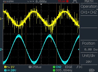
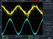
Therefor I tried to measure input/output with an oscilloscope, an learned that the L25D reverse the phase from input to output. Anyone else who has discovered this?
The "prove" is in the picture below, keep in mind that for test purposes I used a small transformer 2x30V/120VA. I normally use 2x45V/500VA for two amplifier connected to a Klipsch RF-82.
I've built 6 of these amplifiers now, and 2 L15D to power my surround system. I use them to bi-amp front an center, while the L15D's are connected to the surround speakers.
The "processor" is a Yamaha RX-A810, receiver with pre-out. Last time I ran YAPO, room correction, I got the message that all my speakers where miswired.
Therefor I tried to measure input/output with an oscilloscope, an learned that the L25D reverse the phase from input to output. Anyone else who has discovered this?
The "prove" is in the picture below, keep in mind that for test purposes I used a small transformer 2x30V/120VA. I normally use 2x45V/500VA for two amplifier connected to a Klipsch RF-82.
Attachments
I'm thinking about stacking two smps500r with long standoff's. They will be fairly close together to a maximum stack height of 95-100mm - each psu being 44mm tall.
Would this be advisable?
An alternate idea was to use a single smps800re, but that being a bit large and with little space in the case") I'll have to raise the psu and have some part of the amp modules (l25d) underneath, and perhaps a speaker prot. under also.
I'll have to raise the psu and have some part of the amp modules (l25d) underneath, and perhaps a speaker prot. under also.
Would there be any concerns with this configuration, perhaps some radiated noise issues?
Would this be advisable?
An alternate idea was to use a single smps800re, but that being a bit large and with little space in the case
I'll have to raise the psu and have some part of the amp modules (l25d) underneath, and perhaps a speaker prot. under also.Would there be any concerns with this configuration, perhaps some radiated noise issues?
mesc: the only possible issues are regarding safety, if the smps is not bolted tighthly and will move inside the enclosure in case of shock or drop, and the other issue is the heat dissipation. the smps below will get hotter if there is no airflow and is used for high continuous power. If there is a bit of airflow, I suggest to mount them face-to-face, either PCB-PCB or components to components and PCB's at the exterior and use a small fan to keep the temperature low.
the EMI at 10cm from the board or more is pretty low to not interfere even with preamplifier circuits. in near proximity to transformer the field is intense due to transformer construction and is not recommended to route wires at less than 5cm from transformer, and also, do not try to shield the board or the transformer directly.
cod3gen, pls resend mail and mention that is you, I can't recognize just after the nickname.
If i mount them vertically, pcb-pcb with the heatsinks on top and venting holes in the chassis.
Should be ok i think..?
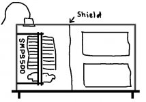
But also you mention no direct shielding. I'm not sure what that means. Can I have a section for psu, separated by a wall? The wall will be fairly close to the outer module though, about 10mm.
I've made a rough illustration. The distances here is not correct, it will be much tighter.
Should be ok i think..?
But also you mention no direct shielding. I'm not sure what that means. Can I have a section for psu, separated by a wall? The wall will be fairly close to the outer module though, about 10mm.
I've made a rough illustration. The distances here is not correct, it will be much tighter.
Attachments
I sent it through your website.
What the dimensions of SMPS3K6QR, SMPS2000R? (Should have been added to your product details on webshop)
Whats the difference of the two 800w models?
The 2000, 3600 and 4800w models, are not regulated right?
Using 2pcs of 800W supplies, and 1pcs of for example SMPS3K6QR on the same main power line, would this have any bad effects? Since they are not linked.. Im thinking of EMI problems and things like that..
Dear all,
yesterday I received my SMPS800RE.
Today I was going to check correct operation by measuring main out voltage and aux voltage.
After bridging "Switch" input to get the unit to work, I connected the power plug.
After 3 seconds the mains fuse of the unit blowed.
There was nothing connected to the module than the power plug.
I cannot find any other reason for this than the unit is broken.
Do you have any idea?
Thorsten
Mesc: seems fine, if you can drill some holes on the enclosure for ventilation. the smps has a small thermistor on the mains side power transistors which will shut-down the smps if the temperature rise above 85*C which can happen in a sealed enclosure. the highest normal working temperature is about 55-60*C on the secondary diodes heatsink or transformer windings. durring tests, I overload the SMPS500R and keep in a seled enclosure till it reach the OT tripping point to make sure will work properly. but of course this is an exceptional situation and should not be encountered often in real life situation, because it shortens the life of capacitors if they are exposed to high temperatures and high ripple current for long periods of time. nice drawing, btw
Cod3gen: please, send the mail again. haven't received anything. if you use a mail address of a less often used domain, private or something which for some reason was in a spam blacklist, the mails are filtered.
the size of the boards are as follows:
SMPS3600QR - 266X140mm and 55mm tall
SMPS2000R - 200X120mm the board only, and the heatslug version. the heatsink version has the heatsink extending 30mm outside the board, so consider 150mm wide. the height is ~40-45 mm depending on the capacitors used.
SMPS4K8 - 200x200mm and 58mm tall
SMPS2000R, SMPS800RE, SMPS800RS, SMPS500R, SMPS500RS, SMPS500RxE, SMPS300RE, SMPS300RS, SMPS240R has regulated and adjustable output voltage, the output voltage is stable from near zero load to maximum load while mains voltage varies within 210-240V or 100-125V AC.
SMPS3K6, SMPS4K8, SMPS200QR, SMPS500QR are the only Unregulated output voltage SMPS (I prefer to call them electronic transformer, although inproper name) where the output voltage cannot be adjusted by user, it is proportional with the mains input voltage and it decrease with load by a 5-10% from zero to maximum load depending on several factors among with them being the mains network impedance.
TriplePower, we already spokt by mail and arrange unit replacement.
.
.
.
.
.
TriplePower, we already spokt by mail and arrange unit replacement.[/QUOTE]
That´s correct. I posted this before I received feedback from you.
p.s.: I am still not clear about the poin assignment of the IRS2092 Stereo Amp:
Connexelectronic
Can somebody please help me and show the complete pin assignment of all connectores?
@Cristi:
You could provide a piece of paper with the pinning for IRS2092 Stereo amp when shipping. (Or label all pins on the PCB)
Thorsten
.
.
.
.
TriplePower, we already spokt by mail and arrange unit replacement.[/QUOTE]
That´s correct. I posted this before I received feedback from you.
p.s.: I am still not clear about the poin assignment of the IRS2092 Stereo Amp:
Connexelectronic
Can somebody please help me and show the complete pin assignment of all connectores?
@Cristi:
You could provide a piece of paper with the pinning for IRS2092 Stereo amp when shipping. (Or label all pins on the PCB)
Thorsten
Hello,
Is there a "SMPS2000RxE" version of the SMPS2000R in the works? I would like to build a 5 channel amplifier using your IRS2092 based modules (probably your CxD500) and, in that case, would need the other differential and DC voltage required by that design.
Is bus pumping significant enough that i should consider doing a 6 channel and reversing three of the channels?
Do you have any DIY chassis recommendation with appropriate heat sinking for a multi-channel design using this unit. You mention 12-24 modules in a chassis and wondered if there were any reference design documents etc.
Thanks,
Chris
- Status
- This old topic is closed. If you want to reopen this topic, contact a moderator using the "Report Post" button.
- Home
- More Vendors...
- Connexelectronic
- Switched Mode Power Supplies (SMPS)