The BIPS modules requres very low current, up to 10mA and the SMPS500R auxilliary voltage can supply 3 modules without problem. the only thing what might need to change is to lower the value of the resistors connected between supply and zenner diodes.
The LM4702 amplifiers can be supplied by SMPS500R as i mentioned before, and they can be ordered with higher aux. voltage to supply the driver of the amplifier separately.
The LM4702 amplifiers can be supplied by SMPS500R as i mentioned before, and they can be ordered with higher aux. voltage to supply the driver of the amplifier separately.
The A350SMPS is quasi resonant Half-Bridge unregulated output SMPS and the SMPS250 is resonant Flyback regulated output SMPS. for better performances i recommend SMPS250 for class D and T amplifiers with power level of up to 100W per channel or 2 modules with 70W per channel each module.
The actual version of A1000SMPS can provide both differential voltages in range of +-45 to +-58V, different values on request, as well as single voltage in range of +45V to +60V, other values on request.
Aso, a higher power SMPS is under development, but, as we know, it will be available for sale just when will be completed, fully tested and first batch on stock.
Aso, a higher power SMPS is under development, but, as we know, it will be available for sale just when will be completed, fully tested and first batch on stock.
It might be a cold start overcurrent which could kill the thermistor. that can explain the noise and the fact that the fuse is not burned. can you measure the thermistor, with a multimeter, should have about 10R when is cold. make sure that you disconnect everything before measure. i wont' guide you to measure anything else which implies to connect the smps to live mains. if you cannot find the problem, just send me back and i will replace it.
thanks for the help. referring to the pcb, could you tell me which one is the thermistor ?It might be a cold start overcurrent which could kill the thermistor. that can explain the noise and the fact that the fuse is not burned. can you measure the thermistor, with a multimeter, should have about 10R when is cold. make sure that you disconnect everything before measure. i wont' guide you to measure anything else which implies to connect the smps to live mains. if you cannot find the problem, just send me back and i will replace it.

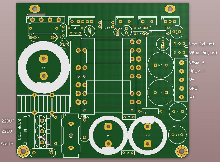
edit : I looked again the board carefully: it seems that a small component (R2 on pcb) is blown.
Last edited:
the thermistor is R2, exactly the one which you said. in the attached image, has the oblong footprint just under the rectifier bridge and C24.
replace the thermistor with a new one, same value, and for better reliability you can consider a bigger size. the value is 10R. the code for a bigger one is NTC 10D-13. after you replace, leave about 12-15mm long legs from the pcb to allow heat dissipation without overheating the board. in normal working conditions the thermistor gets very hot, over 60*C.
replace the thermistor with a new one, same value, and for better reliability you can consider a bigger size. the value is 10R. the code for a bigger one is NTC 10D-13. after you replace, leave about 12-15mm long legs from the pcb to allow heat dissipation without overheating the board. in normal working conditions the thermistor gets very hot, over 60*C.
ok will do.the thermistor is R2, exactly the one which you said. in the attached image, has the oblong footprint just under the rectifier bridge and C24.
replace the thermistor with a new one, same value, and for better reliability you can consider a bigger size. the value is 10R. the code for a bigger one is NTC 10D-13. after you replace, leave about 12-15mm long legs from the pcb to allow heat dissipation without overheating the board. in normal working conditions the thermistor gets very hot, over 60*C.
10R Thermistor is actually not that easy to find
I could not find your exact reference. I've found some at this website in english at farnell
They differ by the current and by "BETA value" which I have no clue what it means
.Would this one do ?
Code:
EPCOS B57238S100M
    * THERMISTOR, NTC, 10R, 5A
    * Thermistor Type:NTC
    * Resistance:10ohm
    * Beta Value:1208
    * Beta Value Lower Limit Temperature:25°C
    * Body Diameter:16mm
    * Case Style:Radial
    * Lead Length:32mm
    * Lead Spacing:7.5mm
    * Max Current:5A
    * Max Operating Temperature:170°C
    * Max Power Dissipation Ptot:3.9W
    * Operating Voltage:265V
    * Resistance Tolerance:± 20%
    * Series:B57238
* Temperature Upper Limit, Beta Value:100°CThe thermistor used for this smps is not a "sensitive" choice. in fact, any thermistor which have nominal resistance at 25*C between 5 to 10R and can withstand at min. 3A can be used. the size should be between 9 to 13mm, bigger one will not fit on the tight space.
i just narrow the search and there are 3 types which can be used.
Your Search Results | Farnell United Kingdom
i just narrow the search and there are 3 types which can be used.
Your Search Results | Farnell United Kingdom
thanks. for some reason, the link does not work on my side. Could you give me the part numbers ?The thermistor used for this smps is not a "sensitive" choice. in fact, any thermistor which have nominal resistance at 25*C between 5 to 10R and can withstand at min. 3A can be used. the size should be between 9 to 13mm, bigger one will not fit on the tight space.
i just narrow the search and there are 3 types which can be used.
Your Search Results | Farnell United Kingdom
i will post the direct link to the parts: http://uk.farnell.com/ge-sensing-thermometrics/cl-120/ntc-thermistor/dp/1707218
AMETHERM|SL10 10002|NTC Thermistor | Farnell United Kingdom
be very careful when you install the new thermistors. after plug-in the smps the big capacitor will be charged at +300V, then will take few minutes to discharge. wait until is completely discharged, and only then can work with the board.
AMETHERM|SL10 10002|NTC Thermistor | Farnell United Kingdom
be very careful when you install the new thermistors. after plug-in the smps the big capacitor will be charged at +300V, then will take few minutes to discharge. wait until is completely discharged, and only then can work with the board.
ok. thanks for the advice : good for my health !i will post the direct link to the parts: GE SENSING / THERMOMETRICS|CL-120|NTC Thermistor | Farnell United Kingdom
AMETHERM|SL10 10002|NTC Thermistor | Farnell United Kingdom
be very careful when you install the new thermistors. after plug-in the smps the big capacitor will be charged at +300V, then will take few minutes to discharge. wait until is completely discharged, and only then can work with the board.
I'll pick this one : similar or better than the suggested. A bit more expensive, but available here in Europe to avoid the 16GBP shipment costs from the US!
EPCOS|B57235S100M|THERMISTOR, NTC | Farnell United Kingdom
I'll let you know the result of the surgery.
- Status
- This old topic is closed. If you want to reopen this topic, contact a moderator using the "Report Post" button.
- Home
- More Vendors...
- Connexelectronic
- Switched Mode Power Supplies (SMPS)