Oh, man, are-you trying to use a SMPS with is a powerful radio emitter without fully shielded (separates) enclosures for both SPMS and power amp ?
i've tried to reproduce your problem without any success. i was using 2 SMPS800R, one set for +-60V with a TA3020 amplifier and one for +-48V with a LM4702SAP15 amplifier. both without any noise, even if the power supply was few cm away from the amplifier module.
i left the GND to Earth disconnected and there was no noise as well.
i'm trying to imagine what can happen, and the first thing which i believe could be the problem, is that the PSRR of the amp is too low, and the output ripple of the power supply when operates at low load in burst mode is amplified and creates that noise.
i offer to fix your problem if you can send me back both the power supply and the amp. i'm very curious, since i never encountered this problem.
Got my smps800r.
Soldered in the IEC. DVM tested for connectivity at different points on the AC side of the board. Tested OK.
Plug in and no power up. Test output DC, no volts.
Does something else need to be soldered in?
Forgot to add in the on/off switch, now it works fine.
"Wire amp" SMPS
Hi Cristi,
Over at the wire amp thread you indicated that you'll be designing a custom SMPS for the amp project. For best performance, a regulated supply can be used for the input stage. But this regulated supply has a higher voltage than the main voltage. Is this possible with your supplies?
Hi Cristi,
Over at the wire amp thread you indicated that you'll be designing a custom SMPS for the amp project. For best performance, a regulated supply can be used for the input stage. But this regulated supply has a higher voltage than the main voltage. Is this possible with your supplies?
Forgot to add in the on/off switch, now it works fine.
This new SMPS800R (different circuit board and a few different parts) has a much lower noise floor than my old SMPS800R (From March 2011).
Amps now sound much cleaner and clearer. Less noise.
I didn't expect any change. Good job!
I'm not gonna rise the price, even i have enough orders to do so, i even consider to bring few more models, some lower power versions with lower price than any alternative, including the Moneywell bricks.
Cristi,
A smaller 250W SMPS would be perfect for Tripath amps. I wouldn't worry about competing on price; the Meanwell clones are becoming more expensive anyway.
")
One thought, however: a rectangular 1U form factor (with the narrow side about 75mm or so) is easier to fit inside a small case than a 100mm x 100mm square one. Your SMPS180QR is a good example, although a unit that's 75mm x 125mm (or longer) would work just as well.
No need of high efficiency for the low currents of input stages, a little and cheap linear supply will offer less HF annoyance here, and total isolation, IMHO.Hi Cristi,
Over at the wire amp thread you indicated that you'll be designing a custom SMPS for the amp project. For best performance, a regulated supply can be used for the input stage. But this regulated supply has a higher voltage than the main voltage. Is this possible with your supplies?
The best of the two worlds.
Almost all the modules which i made have several revisions, and each new batch will have something improved compared to previous one, without increasing the price.This new SMPS800R (different circuit board and a few different parts) has a much lower noise floor than my old SMPS800R (From March 2011).
Amps now sound much cleaner and clearer. Less noise.
I didn't expect any change. Good job!
unbelivable, there is manual available for this power supply and this is your second SMPS800RForgot to add in the on/off switch, now it works fine.
I will consider this aspect, and if i have enough time and there are few more requests, i will do it. how about a thin one, very thin....Cristi,
A smaller 250W SMPS would be perfect for Tripath amps. I wouldn't worry about competing on price; the Meanwell clones are becoming more expensive anyway.
One thought, however: a rectangular 1U form factor (with the narrow side about 75mm or so) is easier to fit inside a small case than a 100mm x 100mm square one. Your SMPS180QR is a good example, although a unit that's 75mm x 125mm (or longer) would work just as well.
less than one inch ?No need of high efficiency for the low currents of input stages, a little and cheap linear supply will offer less HF annoyance here, and total isolation, IMHO.
The best of the two worlds.
I also proposed this topology on the wire amp thread, a clean linear regulator could deliver a smoother and lower ripple DC voltage.
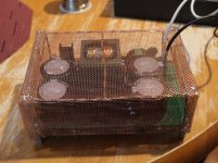
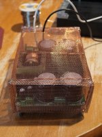
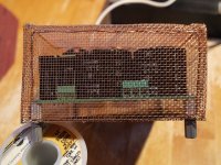
SMPS800R faraday cage
I finished a Faraday cage for one of my SMPS800R and experimented with an additional ferrite core.
Below are a couple of pictures of the cage with the SMPS800R inside.
When I added the ground lift resistor and wired this all up to the Beta24 amplifier module I am working on everything went fine. The switching ripple was down to about 90mV which is not great but the overall noise was okay.
I had also bought Material-W ferrite cores with and tried to reduce the ripple further with a couple of turns but somewhat to my surprise that brought the ripple back up to almost 300mv. I would be grateful if someone could explain that.
I took a closer look at a 1Khz signal and that worked at lower volume but when I increased the volume and in consequence the power draw the 8 amp fuse on the SMPS800 popped! The SCK15-2R58 NTC Thermistor for inrush limiting had cracked in 2 pieces.
I am at a loss why that would happen when increasing the volume? First thing I need is a replacement for the Thermistor. Mouser or Digikey don't seem to carry this brand. Any suggestions for a supplier or a mouser/digikey code for a suitable replacement. I looked up the one below but I am not sure whether that is a good replacement.
B57238S259M EPCOS Thermistors - NTC
Attachments
Last edited:
Thomas, please use the same type or higher current rating for the thermistor. make sure the power supply mains cable has no poor contact which can disconnect and connect again while working. if this happens, the thermistor is hot when the power is connected again and this might lead to damage. if you can't find it locally, just mail me and i can send you.
the cage should be connected to GND and earth thru all the screw legs of the power supply. measuring the ripple is tricky, and can show wrong values if is done improperly. also, the ripple at no load is higher than at moderate load because the power supply works in burst mode when there is no load.
the cage should be connected to GND and earth thru all the screw legs of the power supply. measuring the ripple is tricky, and can show wrong values if is done improperly. also, the ripple at no load is higher than at moderate load because the power supply works in burst mode when there is no load.
Thanks Cristi,
I read the links you pointed me to earlier in the thread but I am not sure how these measurement techniques apply to actually driving an amplifier with this supply.
I measured the ripple while playing a 1Khz signal through the amp at medium volume. I connected the probe and clip at the voltage supply points for the amp which I think is the right place to do it. I might have another look at the output of the filter caps. The scope was AC coupled with bandwidth limited to 25Mhz.
I also checked the 1 Khz output signal at the speakers and that looked remarkably clean. Without the cage you can easily see the ripple riding on the 1Khz output signal.
I order the thermistor and report back when I have both channels assembled.
Cheers
Thomas
The UCD400 module ON/Off switch pin must be pulled low to activate the module. the easiest way is to connect this pin to GND. supplying voltage from aux output is not the way to do-it. there are two ways to implement the turn-on. the best one is to use a general purpose NPN transistor with emmiter connected to GND collector at ON/Off pin and base to +12V aux tru a 10K resistor. in addition, a 1k-2k2 resistor between base and emmiter should be connected and if delayed turn on is needed, a 470uF cap as well in parallel with BE junction.
Would an 11K resistor be OK (I have some spare
)? Also, with a 470uF electrolytic cap, which way around should I connect it?Thanks.
"Off course the ripple values can be improved by using an additional LC filter, on each rail."
I am using the SMPS800R power supply, and would like some ideas for improving the output noise/ripple. I'm powering an audio amplifier and looking for any and all ways to improve this power supply.
In an earlier post, Cristi mentioned adding an additional LC filter for each output rail. I would be most appreciative of hearing some ideas of what type of circuit and what values to use in order to build this. This would be for a +/-68V output.
Thanks for any suggestions.
Would an 11K resistor be OK (I have some spare
Thanks.
Anyone?
I'm going assume that the 1K difference in resistor value won't matter and that the positive pin of the capacitor should be connected to the transistor base pin and the negative to the emitter pin. I suppose the worst case scenario is that the cap explodes!
BTW, Cristi, I received my power supplies today and am very pleased with them. They look very well constructed and are just the right size
BTW, Cristi, I received my power supplies today and am very pleased with them. They look very well constructed and are just the right size
Hi Cristi
I posted this in the L20D amplifier thread but here seems a more appropriate place since the questions are related to your product.
I bought a bunch of the L20D amplifier off ebay for use in an active loudspeaker and was looking to pair them with an SMPS from Connex.
Would a single SMPS2000R (2000w rated) model be OK powering all six L20D modules?
Can I connect the modules directly the PSU and finally I take it I should specify 70v output on the SMPS?
Duffy,
i think i explained earlier how to build that circuit, i will search tomorrow and if i cannot find i will draw a simple schematic with values.
Shin,
The SMPS2000R can supply several amplifier modules, if their total output power is within the nominal output power of SMPS2000R. The desired output voltage should be specified when placing the order.
- Status
- This old topic is closed. If you want to reopen this topic, contact a moderator using the "Report Post" button.
- Home
- More Vendors...
- Connexelectronic
- Switched Mode Power Supplies (SMPS)