Hi Cristi,
I have ordered some NXD TDA8950 boards from you. While I'm waiting for the boards to land i Denmark, I'm, looking for the rigth transformator. What will you recommend - minimum and optimum?
I'm looking at 2x25 volt 200 VA minimum per 2 channel board.
I have ordered some NXD TDA8950 boards from you. While I'm waiting for the boards to land i Denmark, I'm, looking for the rigth transformator. What will you recommend - minimum and optimum?
I'm looking at 2x25 volt 200 VA minimum per 2 channel board.
Last edited:
Hi Brian
the proper transformer for TDA8950 amplifiers must provide an ac voltage in range of 2x22V to 2x26V and at least 4A, and if possible 5-6A to provide enouch current to the amplifier when is used with low load impendance. the one which you have chosen seems within the specs, with minimal power.
an alternative is to use a SMPS, lightweight and with regulated output voltage. Connexelectronic
the price is similar with a mains transformer
Input pins:
I'm not quite sure what to do with the middle pin (pin 3). I have read the instructions.
Maybe you could make at drawing on how to cable the module.
Something like this
http://www.lcaudio.dk/pdfs/800XEassembly230V-DK.pdf
I'm not quite sure what to do with the middle pin (pin 3). I have read the instructions.
Maybe you could make at drawing on how to cable the module.
Something like this
http://www.lcaudio.dk/pdfs/800XEassembly230V-DK.pdf
Cristi,
with the TDA892xV2 boards, TDA8920TH IC, bridged into 8ohms:
- is it possible to get the full 135W output (or close) using +19dBU balanced input signal?
- is the BIPS board required to allow the use of balanced input signal?
- is it reasonable to run 2x such modules off the one 250W (400W peak) SMPS that you sell? (Music signal only)
Thanks
Brian,
pin 3 of the TDA89xx amplifier is the Mode pin. when the voltage on this pin is 0, the amplifier is muted and in stang by. when the voltage is about 2-3 V the amplifier is in Mute mode and when the voltage is >4V the amplifier is working normally. please read the manual of the v1 for more details. they share the same schematic, just the layout is different.
fb,
+19dB is much higher level than the amplifier requires and you need an attenuator to reduce to the proper level.
for full balanced input you can use either BIPS or modify the amplifier, the ic already has balanced input, but is not used and connected to GND.
the smps can provide the peak power for 2 modules if you use one for low and one for mid-hi freq. it might need to add some extra capacitors.
I have read the manual, and know about the voltages, but do I need to supply 4 volts to the pin? I thought the board would work with just one normal 25-0-25 volt transformator?
The board has a simple regulator with zenner diode which provide this voltage. by default, the amplifier is unmuted. when you connect the pin 3 to GND the amp will mute.
The board has a simple regulator with zenner diode which provide this voltage. by default, the amplifier is unmuted. when you connect the pin 3 to GND the amp will mute.
Thanks, thats what I hoped for.
Next question. The NXD chip and the rectifier bridge is not the samme hight. When I'm using the mounting holes on the same heatsink, then there is a hight difference and I'm afraid that the NXD chip will not have full contact. The NXD chip is the lower one, and therefor som downforce should be applied to the screws, for the chip to get full contact.
Is this a problem, or can I go forward with both chip and rectifier bridge on the same heatsink?
the height difference of 0.2-0.3 mm between the IC and rectifier will be compensated by the insulation sheet which must be placed under the IC. be careful that the IC pad should not touch the GND and must be insulated.
Thanks again for a quick reply. In the manual it's also mentioned that you could use isolation on the rectifier bridge! Maybe it should be pointet out, that the hight difference should be eiminated with the isolation on chip only?
Sorry for all my questions, but it's not the first time i build class d, and I know they can be unstable if not handled correctly.
On additional question. Can I have the amp switched on, with out load on the speaker output. Many class d amplifier don't like to be switched on with out any load on the speaker output.
if you want to use the amplifier without load, it might need to increase the value of the capacitor from the zobel network up to the value of the LC filter capacitor.
Again the pin 3 ...
Hello,
I'm making a DIY amplifier with a TDA8920BTH and I'm not sure what to do with the pin 3 😕
When I read the doc, I understand that I have to provide a 5v DC to make the amplifier operating but when I read your post ... I'm confused because you say the amplifier is unmuted by default.
I'm also using this pre-amplifier in the box : Préamplification - LITE MV04 - Contrôleur de Volume passif Motorisé 2 ou 4 canaux so I could use the 5v LED SOURCE to provide this signal...
Thx for your help. 🙂
The board has a simple regulator with zenner diode which provide this voltage. by default, the amplifier is unmuted. when you connect the pin 3 to GND the amp will mute.
Hello,
I'm making a DIY amplifier with a TDA8920BTH and I'm not sure what to do with the pin 3 😕
When I read the doc, I understand that I have to provide a 5v DC to make the amplifier operating but when I read your post ... I'm confused because you say the amplifier is unmuted by default.
I'm also using this pre-amplifier in the box : Préamplification - LITE MV04 - Contrôleur de Volume passif Motorisé 2 ou 4 canaux so I could use the 5v LED SOURCE to provide this signal...
Thx for your help. 🙂
Did I get it for the cabling in Stereo or Mono (BTL) ?
What about the third proposal : would this work with a stero source ?
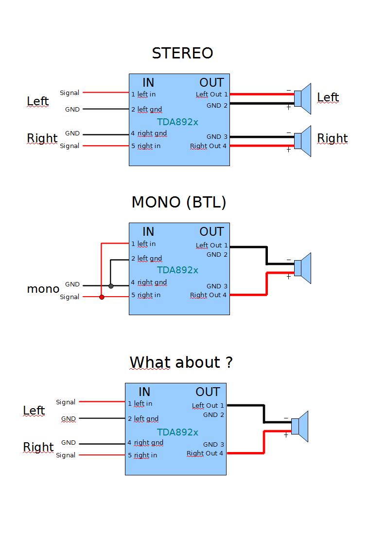
What about the third proposal : would this work with a stero source ?
pin 3 is already biased at 5V from a simple regulator, so the amplifier is in "play" mode. you can measure the voltage on the pin 3 with a multimeter. i can't see the link which you post due to the internet filters, pls send me by mail relevant infos.
first two setups are fine, the last one is not. if you supply the amp with stereo signal and you pick-up the signal from the outputs, like in BTL mode you will get some low freq. which are in phase and mid-hi will be distorted or out-of-phase. in addition to this, is likely that the amplifier will run in overvoltage protection mode due to pumping wich can ocure with such setup. you should not use-it like this.
first two setups are fine, the last one is not. if you supply the amp with stereo signal and you pick-up the signal from the outputs, like in BTL mode you will get some low freq. which are in phase and mid-hi will be distorted or out-of-phase. in addition to this, is likely that the amplifier will run in overvoltage protection mode due to pumping wich can ocure with such setup. you should not use-it like this.
Thanks Cristi. I would like to build an amp that can be used either in stereo or in mono. I'll put a switch to toggle input betwen schema 1 and 2.first two setups are fine, the last one is not. if you supply the amp with stereo signal and you pick-up the signal from the outputs, like in BTL mode you will get some low freq. which are in phase and mid-hi will be distorted or out-of-phase. in addition to this, is likely that the amplifier will run in overvoltage protection mode due to pumping wich can ocure with such setup. you should not use-it like this.
Any single channel for +/- 60V + volt supply amp? To replace a dead amp in sub...
yes. i'm working at that now, coming at the beginning of the next month. IRS2092 based class D amp.
- Home
- More Vendors...
- Connexelectronic
- Class D Audio Amplifiers