Hi,
1. Ok so i will mount it with metal screws in all the mounting holes!
2. Mica insolation between chip and heatsink
3. I will isolate the heatsink from the metal chasis in my HTPC
4. i will seperate the two modules be cutting the heatsink into to pieces.
I hope thats the correct assumptions")
1. Ok so i will mount it with metal screws in all the mounting holes!
2. Mica insolation between chip and heatsink
3. I will isolate the heatsink from the metal chasis in my HTPC
4. i will seperate the two modules be cutting the heatsink into to pieces.
I hope thats the correct assumptions
Hi,
1. Ok so i will mount it with metal screws in all the mounting holes!
2. Mica insolation between chip and heatsink
3. I will isolate the heatsink from the metal chasis in my HTPC
4. i will seperate the two modules be cutting the heatsink into to pieces.
I hope thats the correct assumptions
the reason why i recommend to use all the screws is that the GND copper pour has a star connection on the rectifier bridge hole.
at 4. the measure is effective only if the modules are using separate supply or at least separate windings on the mains transformer, to not have a common GND on the supply path, just at the input connectors.
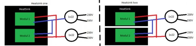
Here is how i would like to connect the supply:
An externally hosted image should be here but it was not working when we last tested it.
I have mounted the modules with only metalscrews in all holes, but i have done it on the same heatsink as shown "Heatsink one", but is it nescesarry to cut the heatsink into two pieces as shown on "Heatsink two", due to the way i connect the trafo's?
Please upload the picture here, i cannot see the picture in the link posted.
i'm not very sure what you mean by using 2 heatsinks, maybe the picture explain this, but i recommend to use just a single heatsink on which the amplifier board is installed, making the whole assembly very compact and with good thermal conductivity.
i'm not very sure what you mean by using 2 heatsinks, maybe the picture explain this, but i recommend to use just a single heatsink on which the amplifier board is installed, making the whole assembly very compact and with good thermal conductivity.
.Please upload the picture here, i cannot see the picture in the link posted.
i'm not very sure what you mean by using 2 heatsinks, maybe the picture explain this, but i recommend to use just a single heatsink on which the amplifier board is installed, making the whole assembly very compact and with good thermal conductivity.
An externally hosted image should be here but it was not working when we last tested it.
I think the picture will explain what i mean. (i have to modules)
Attachments
Now i understand what you mean. each amplfier board to have it's own heatsink. you should do this way if you have 2 heatsinks, and when install them try to isolate them from the case gnd, so that the gnd will be start connected at the input only.
i see that the transformers are 1x22V ???? can you rewind them to have 2x19V AC and to use a transformer for each module ? this will avoid other kind of problems related to the power supply.
i see that the transformers are 1x22V ???? can you rewind them to have 2x19V AC and to use a transformer for each module ? this will avoid other kind of problems related to the power supply.
Now i understand what you mean. each amplfier board to have it's own heatsink. you should do this way if you have 2 heatsinks, and when install them try to isolate them from the case gnd, so that the gnd will be start connected at the input only.
i see that the transformers are 1x22V ???? can you rewind them to have 2x19V AC and to use a transformer for each module ? this will avoid other kind of problems related to the power supply.
Okay i have one big heat sink and two smaller ones, i will just install them on seperate heatsinks and isolate the gnd, no problem at all.
I have just for now installed one module, and it plays very well so far. But when i turn the module on there are some "STRANGE NOISE" on the output, dosnt sound good in the speakers. Do you have any idea on this problem?
Sorry i think i was to fast: I will try to add a cap between mute and GND, first... Thank you for the great help so far, good job!!
Last edited:
Okay i have one big heat sink and two smaller ones, i will just install them on seperate heatsinks and isolate the gnd, no problem at all.
I have just for now installed one module, and it plays very well so far. But when i turn the module on there are some "STRANGE NOISE" on the output, dosnt sound good in the speakers. Do you have any idea on this problem?
Sorry i think i was to fast: I will try to add a cap between mute and GND, first... Thank you for the great help so far, good job!!
Try to add a 47-100uF capacitor between the Mode pin and GND. while this capacitor will charge slowly, the amplifier will toggle between Off, Mute and Play and eliminate the noise.
on the new version of the TDA89xx amplifier i already integrate the capacitor on the board, to avoid complications and headdache.
Hi Christi
I am interested in buying the DA-1 class d amp but cannot find many
specifications. What is the THD of this amp with a 4ohm and 8ohm load? I was after a low thd amp that can drive a pair of 4ohm speakers.
The THD at 4 Ohms, is below 0.1% at 400W and 250W at 8 Ohms. there is a short form description located here: http://www.connexelectronic.com/documents/DA-1_Short_Form_Description.pdf
I just received my IRS2092 based amp Connexelectronic but after first visual inspection I have noticed that there is one jumper wire missing.
It's the one in front of Q105b that connects the emmiters of Q105b and Q105a.
Should this wire be fitted or not?
It's the one in front of Q105b that connects the emmiters of Q105b and Q105a.
Should this wire be fitted or not?
The jumper is installed only at low power version where only one transistor and zenner diode for voltage regulator for negative+ rail should be used. if you follow the track you will see that this jumper is between the emitors of the Q105A and Q105B transistors, and can supply both amplifier stages from a single voltage regulator. on medium-high power versions i decided to use separate regulators for each channel, so the jumper should not be soldered. supplying each channel from different regulator gives better performances, and less crosstalk.
L.E. just noticed that you told me about the voltage which you want to use for test, and i consider that is useful for others to mention that the amplifier must be supplied with the voltage marked on the pcb for the specified power rating. if the voltage is lower or higher with 10-15% the amplifier will not start, due to the undervoltage and overvoltage protection which will mute the amp till the voltage will be within range. for example, the 400W version should be supplied with +-64V. a voltage below +-51V will Mute the amp, as well as a voltage above 72V. moreover, if the maximum voltage is above +-48V for 100W version, +-72V for 200W, and +-92V for 400 and 500W versions, there is a risk of permanent damage of the power transistors and ic because of exceeding the maximum voltage.
L.E. just noticed that you told me about the voltage which you want to use for test, and i consider that is useful for others to mention that the amplifier must be supplied with the voltage marked on the pcb for the specified power rating. if the voltage is lower or higher with 10-15% the amplifier will not start, due to the undervoltage and overvoltage protection which will mute the amp till the voltage will be within range. for example, the 400W version should be supplied with +-64V. a voltage below +-51V will Mute the amp, as well as a voltage above 72V. moreover, if the maximum voltage is above +-48V for 100W version, +-72V for 200W, and +-92V for 400 and 500W versions, there is a risk of permanent damage of the power transistors and ic because of exceeding the maximum voltage.
Last edited:
Thanks for the fast and very help full reply.
You are of course right. I just checked IRF reference design 7 and confirmed that.
Regarding Under voltage protection, I guess this can be changed by altering the zener that sets the threshold.
Last but not least, overall it's a very well designed kit with excellent construction quality and very well packed!
Yes, and you can just mention this when you order them to make sure about. btw, i have replied to this answer from your mail sent in 23 sept. seems that you haven't got that mail. for you and not only, if i don't reply in one-two days to a mail, please resend or send me pm through forum, i have more than 1000 mails every month and some of them are failed to deliver probably due spam filters.
- Home
- More Vendors...
- Connexelectronic
- Class D Audio Amplifiers