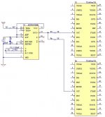
I fried my TDA892x Amp V2 ") rectifier - and + markings interchanged)
rectifier - and + markings interchanged)
I was to test one of my TDA892x Amp V2's yesterday, but the only sound it managed to produce was a loud bang ! as one of the large filter caps blew.
I had made a tiny modification to it and was caught by a mistaken rectifier polarity indication on the PCB. It was to be connected to a DC supply and I didn't want the voltage drop of the mounted rectifier. Out came the rectifier, and it was replaced by two little jumpers. So far so good, + to + and - to - and here you go. No output, and I soon realised the psu produced some alarming ticking sounds (current limit). Then blew one of the caps, before I managed to switch power off.
Investigation soon revealed that the rectifier's + marking on the PCB was actually the -.
I assume this amp is fried, will know for sure later today. Just thought I'd share this with you, as I'm possibly not the only one thinking of connecting a DC supply to these amps (and wanting to avoid the energy and power loss of the superflous rectifier).
The good thing was, the psu (also a Connexcelectronic one) survived ;-).
rectifier - and + markings interchanged)I was to test one of my TDA892x Amp V2's yesterday, but the only sound it managed to produce was a loud bang ! as one of the large filter caps blew.
I had made a tiny modification to it and was caught by a mistaken rectifier polarity indication on the PCB. It was to be connected to a DC supply and I didn't want the voltage drop of the mounted rectifier. Out came the rectifier, and it was replaced by two little jumpers. So far so good, + to + and - to - and here you go. No output, and I soon realised the psu produced some alarming ticking sounds (current limit). Then blew one of the caps, before I managed to switch power off.
Investigation soon revealed that the rectifier's + marking on the PCB was actually the -.
I assume this amp is fried, will know for sure later today. Just thought I'd share this with you, as I'm possibly not the only one thinking of connecting a DC supply to these amps (and wanting to avoid the energy and power loss of the superflous rectifier).
The good thing was, the psu (also a Connexcelectronic one) survived ;-).
Last edited:
One of the first batches of TDA892x amps has the footprint marking opposite i took that from some old library when i made the board and i discovered at assembly only, i don't remember if only the edge cutting or also the + and - marking, but the bridge was installed correctly. the actual ones are all with correct footprint. send me a mail and tell me what parts do you need to replace.
from page 16 there is some information
http://www.nxp.com/documents/data_sheet/TDA8920B.pdf
http://www.nxp.com/documents/data_sheet/TDA8920B.pdf
TDA892x Sync
The easiest way to synchronize the carrier switching frequency for multiple ic's used within a system is to use HEF4047 Multivibrator as clock generator. then, it's output can feed several ic's. few notes: the maximum number of the TDA892x ic's which can be feed from an unbuffered generator should not exceed 6 pcs. for more, a simple buffer must be used, or multiple buffers each driving few ic's.
to force the external sync. the actual resistor from osc pin to negative supply !!! must be removed, and a 1K resistor from the multivibrator output to each osc input pin of TDA892x must be used. this will bias the osc pin above 0V and provide sync.
as a side note, in most of the cases, the noise have other causes than the lack of sync, mostly the GND loop which is formed between power supply gnd of each module and Input GND. since the signal source is only one, there should be only one GND connected for all the inputs, and since all of them use a single power supply, the power supply GND will be the other end of the GND loop. an alternative solution is to use balanced input, which the ic already has instead of unbalanced inputs. when using unbalanced, one input (inverted or non-inverted) is fed with input signal and the other one is connected to GND, that's where the the loop can be avoided, by feeding with balanced signal, there will be no looped GND reference for the other input.
Attachments
TDA89x0SMPS info
Hi Cristi,
I just ordered one of the TDA8950SMPS units. Could you update the info on the module with the schematic (or send it to me)?
I'm interested in two things,
1) Hookup of the status led indicator
2) Can I tap the power supply for a few milliamps to run a dual op amp as an input pre-amp? (adding in a few voltage regulators of course)
Thanks..
(oh, can you tell me the typical lead time to ship the unit?)
The status LED must be connected with a >1.5K series resistor between pin 4 and GND, pin 3 or 5. same pin is also used to mute the amplifier, so a toggle switch can be added on the same pin to GND. make sure to not load this pin with more than 2mA otherwise the amp will be muted, since the voltage drop.
although i do not encourage to make any modification or tap something on the board which is not available at the connectors, i can tell you how to do that (on your own risk to fry something) the diferential voltage is available on the 4 big caps from the secondary side. just connect on the first two, the closest to the transformer. if you need single rail only, the current draw must be lower than 50mA otherwise might create unbalance.
the transformer has one more aux. winding on the secondary side, which can provide 10-18V if is rectified and filtered. if this is enough, i can tell you how to do it.
Remember that the board have mains live voltage on the primary side !!!! do not do this if you have not enough experience !!!
The board is prepared for shipping, i'm waiting few days for confirmation from the shipping company that the delay nightmare has ended, then i can send it both yours and many others. if you need those mods, email me and i will do them for you.
Thanks, I was originally considering putting an ipod cable interface and supplying a 5V USB charging current, but I switched to just a mini jack so there should not be an imbalance. I am looking to supply +/- 5 V (7805, 7905) at only 10-20 mA or so for a dual op-amp for the input stage (Mix L+R, I'm using the amp as a mono BTL to drive an underwater speaker, it gets driven through an output transformer so it has some isolation.) Yes I am an Electrical Engineer and I have designed and worked with lots of high voltages, so I wouldn't worry too much and I understand any mods are my problem.
I could use the open secondary fairly easily, would that just be the two open pins on the transformer? I can figure that out once I get the unit depending on what the secondary voltages you currently produce.
Does the status output go low when any of the protection circuits cut in (turning the LED off?)
Steve
TA3020V4-400
TA3020V4-400: 0.02% THD+N @ 112w @ 8 OHMS
For my use the TA3020V4-400 would basically be a 100W amp.
Can you post some FR, POWER v THD+N curves? None in the PDF.
Besides one review at your site are there any other comments about how this amp "sounds".
Can it be mounted vertically on the back of a speaker (thermal considerations)?
What is the best "sounding" amp you sell? (low distortion and noise, "audiophile" etc.)
Thanks.
IRS2092 Modular Amplifier
This amp looks very interesting. I see that this is a new product for you. Are they ready to ship now, in all power levels?
I assume that the supply voltage ranges that are mentioned on the product page are (a) the lower voltage is the min to reach that power level and (b) the higher voltage is the max recommended supply voltage for that configuration? Can a slightly lower voltage be used, e.g. for the 400W version, can a DC supply of +/- 58-60V be used without any problems (just lower output power)?
Thanks,
-Charlie
right now i have modules on stock from each power version. the voltages mentioned are the normal operating voltages, below or above, the under-voltage or over-voltage protection will mute the module. to get the nominal power, the module should be supplied at the nominal voltage which is at the middle of the interval. if lower voltage is needed, please contact me to change the UVLO level.
Manuals please
Hi,
Got today my IRS2092 Modular Amplifier [ScalD_Amp] 600W, SMPS500 and SMPS800R. They look great and build quality top notch.
Do you have a manual for these I dont want to burn something accidentaly.
Everything look straight forwarded but I would feel better with some manual.
Thanks
Hi,
Got today my IRS2092 Modular Amplifier [ScalD_Amp] 600W, SMPS500 and SMPS800R. They look great and build quality top notch.
Do you have a manual for these I dont want to burn something accidentaly.
Everything look straight forwarded but I would feel better with some manual.
Thanks
TA3020v4 for bass guitar power amp
I am looking at the TA3020v4 as a power amp for two bass cabinets.
The cabs are 1x12 built around the eminence kappalite 3012LF. Around 450W rms @ 8ohms each.
My plan was to run the module in BTL which should meet my power requirements easily.
My questions are
-Would the TA3020v4 serve my purpose well or is there a better option.
-Would this module be able to withstand Pro audio type usage on a regular basis.
-What differences in performance would I expect between this module and a similarly spec'd PA power amplifier (I am currently using a Crown XTI2000 in dual mono)
Thanks for any help.
Should the capacitor be bipolar, og doesn't that matter. If electrytics is ok, how about polarity (minus to gnd i guess?)
Still no answer!! Type and voltage rating would be nice to know. Is 16 volt enough or 35 volt as the caps onboard? Should it be bipolar or electrolytic or does it matter at all? If electrolytic capacitor what about polarity?
- Home
- More Vendors...
- Connexelectronic
- Class D Audio Amplifiers