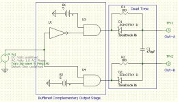
Making the PWM part of the Class D amp is no problem... my problem comes with making the complementary outputs with dead time... I have a Inverting/Non-Inverting 14A mosfet driver but the problem is using this will allow some overlap (bad) how do I make some dead time in the signal?
You havenot done your homework yet
Do some hardwork and search the Class-D section....there are numerous examples of dead time implementing.....
It might be difficult for you to search.....because this forum is now full of newbies T-amp based milky teeth questions such as which is best sounding cap, resistor sound, how to place a volume control, how to solder this, which type of wire sounds best, etc....
The technical section must be made seperate, if the mods want there forum to look healthy
I did find your old thread but I guess I am looking for more of a discrete way of doing things and not all in a chip control.
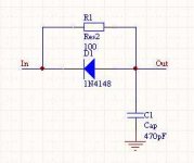
Here is a way to go from a single input to a diferential output.
The gates should be fast to prevent too much propagation delay in the overall amp (not so good in a self oscillating design anyway") )
)
Keep the resistors low in walue to avoide noise pick up problems. Think up to 1k will be no problems.
The gates should be fast to prevent too much propagation delay in the overall amp (not so good in a self oscillating design anyway
)Keep the resistors low in walue to avoide noise pick up problems. Think up to 1k will be no problems.
Attachments
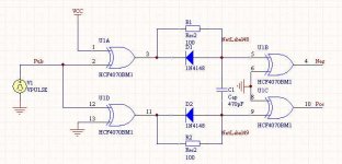
And here is something I found on my PC ... haven't tried it or made a simulation, but I think it works the same as the first one, just using a gate instead of a diode, (and there by providing a better output drive).
Hope it helps
Please do tell more about your project. Pictures, schematics ect.
... haven't tried it or made a simulation, but I think it works the same as the first one, just using a gate instead of a diode, (and there by providing a better output drive).Hope it helps
Please do tell more about your project. Pictures, schematics ect.
Attachments
Thanks for the help... in your second schematic, what are the last 2 XOR gates for? It seems to me that since one input is grounded then when the square wave hits the gate it will always pass and so they do nothing?... I will post some more stuff later as it comes... right now it is all kind of floating around in my head... actually I got the idea to do this because of how many uses a Class D amp really has when you think about it.
I needed to come up with a speed control (with regen breaking) for dual 180W motors used in a radio controlled trash can (it’s a Engineering design project for school)... guess what this is basically a class D amp... I also needed a bass amp for a subwoofer I am building and so Class D came to mind... then again there really is no reason why you could not use the MOSFETs to drive a transformer and you have an SMPS... its the AMP with a million uses
I needed to come up with a speed control (with regen breaking) for dual 180W motors used in a radio controlled trash can (it’s a Engineering design project for school)... guess what this is basically a class D amp... I also needed a bass amp for a subwoofer I am building and so Class D came to mind... then again there really is no reason why you could not use the MOSFETs to drive a transformer and you have an SMPS... its the AMP with a million uses
Just a question here. Even with deadtime, you will need to drain the body diode of charge unless you use unhealthy amounts of deadtime. So you need to use controlled dV/dt (or dI/dt) when turning on the FETs which will impair efficiency if you want to avoid too high noise spikes and EMI. How to best overcome this limitation in amps where you want high efficiency and dont have the option of slow switching? Resonant topology or many phases working at a lower fs?
I use controlled ramps myself, at the cost of efficiency, but it would be nice with a little better efficiency than I have today.
I use controlled ramps myself, at the cost of efficiency, but it would be nice with a little better efficiency than I have today.
Baldin said:Workhorse, that's why we need to help those hwo are actually doing something else than changing tos perfectly good caps to something excotic
But dont you think that the "Fish" haven't done his homework yet....
Again there are more than dozen of threads which have the deadtime implementation techniques featured in them...
- Status
- This old topic is closed. If you want to reopen this topic, contact a moderator using the "Report Post" button.
- Home
- Amplifiers
- Class D
- Dead time how?