Hey all,
Just bought two UcD400's and am about to begin the mods, but the new v6.1 is a little different from the previous versions.
First of all, it has support for either two single opamps or the default dual one. For a differential input the dual will be fine though. It also has (unpopulated) SMD transistors in a configuration between the rails and the opamp outputs (presumably a bias/current gain stage?)
Secondly, it now has two sets of 22uF decoupling caps, one set at the 12V zener-followers, and the other right next to the opamps. A nice addition is that there is now three large pads for connecting the external aux supply right next to the opamps instead of the transistor emitter pins, with the ground one nice and close nearby too.
The purest and easiest should therefore be to connect the aux supply at these pads and just cut off the BDX transistor legs.
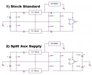
However, there is an RC filter (R=10ohms) between the opamp supply pins and the zener follower's output. The RC is configured that the resistor will "lead" the cap from the opamp side and not the other way round which is puzzling since the default configuration is for the power to come from the transistors. The HEF4093BT runs directly from the positive transistor output.
The attached schematic shows the 12V connections (that I know of) in the stock standard form in 1). The 10ohms and SMD caps are spaced closely since they're placed closely on the board as well i.e. clearly intended as a filter.
So, where would the best place be to connect the aux supply? Is there anything else in the amp that uses the +-12V supplies except the opamp and HEF4093? The safest would obviously be at the transistor pins as specified, but then the RC filter will be configured the wrong way round (it will still work since there're 22uF caps at both sides but the ceramic shunt caps will not follow the resistor). If the rest of the stuff besides the opamps do not draw much current it should be OK, but otherwise it may cause the voltage drop to be too high.
The easiest and purest though would be to keep the entire transistor supply as-is, but remove the 10R resistors and apply the aux supply at the opamp's supply pads, as shown in 2). This way the aux supply also don't have to deal with the HEF4093 and other possible 12V devices. This will work fine, but is there anything besides the opamp that will gain from a cleaner supply? AFIK only the 4093 runs off the 12V besides the opamps, and that will be fine from the zener regulator, but is there anything else?
Ufortunately it seems like the metodology changes with the versions since my UcD180 does it differently. There both the opamps and HEF run directly from the zener supply without any resistor isolation.
Anybody with some inside knowledge? Bruno et al?
Just bought two UcD400's and am about to begin the mods, but the new v6.1 is a little different from the previous versions.
First of all, it has support for either two single opamps or the default dual one. For a differential input the dual will be fine though. It also has (unpopulated) SMD transistors in a configuration between the rails and the opamp outputs (presumably a bias/current gain stage?)
Secondly, it now has two sets of 22uF decoupling caps, one set at the 12V zener-followers, and the other right next to the opamps. A nice addition is that there is now three large pads for connecting the external aux supply right next to the opamps instead of the transistor emitter pins, with the ground one nice and close nearby too.
The purest and easiest should therefore be to connect the aux supply at these pads and just cut off the BDX transistor legs.
However, there is an RC filter (R=10ohms) between the opamp supply pins and the zener follower's output. The RC is configured that the resistor will "lead" the cap from the opamp side and not the other way round which is puzzling since the default configuration is for the power to come from the transistors. The HEF4093BT runs directly from the positive transistor output.
The attached schematic shows the 12V connections (that I know of) in the stock standard form in 1). The 10ohms and SMD caps are spaced closely since they're placed closely on the board as well i.e. clearly intended as a filter.
So, where would the best place be to connect the aux supply? Is there anything else in the amp that uses the +-12V supplies except the opamp and HEF4093? The safest would obviously be at the transistor pins as specified, but then the RC filter will be configured the wrong way round (it will still work since there're 22uF caps at both sides but the ceramic shunt caps will not follow the resistor). If the rest of the stuff besides the opamps do not draw much current it should be OK, but otherwise it may cause the voltage drop to be too high.
The easiest and purest though would be to keep the entire transistor supply as-is, but remove the 10R resistors and apply the aux supply at the opamp's supply pads, as shown in 2). This way the aux supply also don't have to deal with the HEF4093 and other possible 12V devices. This will work fine, but is there anything besides the opamp that will gain from a cleaner supply? AFIK only the 4093 runs off the 12V besides the opamps, and that will be fine from the zener regulator, but is there anything else?
Ufortunately it seems like the metodology changes with the versions since my UcD180 does it differently. There both the opamps and HEF run directly from the zener supply without any resistor isolation.
Anybody with some inside knowledge? Bruno et al?
Attachments
Thanks for the heads up on the new revision.
I can't for my life find any proof of it, but I sure had the impression that the ucd's used +/- 15V, and I've spent a few seconds thinking about how to connect it to the SPS80 SMPS from coldamp which delivers +/- 12 V.
Gotta get of those pills, I guess...
Are we seeing adjustments to adapt to one or more upcoming SMPS'es from hypex?
/Erland
Haven't measured the value of the zener diode used yet, but since the absolute maximum rating of the AD8620 is 13.5V (and believe me it is, I've experienced it once!) +-15V is unlikely. Of course if you used any other opamp, especially now that singles are possible too, +-15V shouldn't be a problem. Just check if the NAND can handle it too.
- Status
- This old topic is closed. If you want to reopen this topic, contact a moderator using the "Report Post" button.
- Home
- Amplifiers
- Class D
- UcD400 aux supply options