I have earlier tried to shield the coils in the charlize. Aluminumtape wrapped around the coils and the tripath-chip. It was a quick test, and did not bother to earth the shield (to bad it doesn't work then ") )
)
This weekend I stumbeld accross the modifications on the Trends Audio TA-10 by Michael Mardis (Thanks Michael )
The modifications looked a lot better than my pitty test, so I gave it another go. I cut the copper plate in the correct height and rolled it in 12mm diameter sylinders (which is the diameter of the coils). A wire is attached to run the shields to ground. I also shielded the chip with aluminumtape.
I did not have high hopes for this mod. I was thinking it should at least make the circuit healtier, and it would not harm applying the tweak. But I was in for a suprise. The sound has improved quite a lot. (I need at least 15% change for my brain to respond ). The whole preformance has got clearer. Sondstage improved in all directions. Expecialy at higher levels. Makes sense since the radiation is greater. For me a successfull tweak.
Are there others who have tried this?
Cheers
Bjorn
)This weekend I stumbeld accross the modifications on the Trends Audio TA-10 by Michael Mardis (Thanks Michael )
The modifications looked a lot better than my pitty test, so I gave it another go. I cut the copper plate in the correct height and rolled it in 12mm diameter sylinders (which is the diameter of the coils). A wire is attached to run the shields to ground. I also shielded the chip with aluminumtape.
An externally hosted image should be here but it was not working when we last tested it.
An externally hosted image should be here but it was not working when we last tested it.
I did not have high hopes for this mod. I was thinking it should at least make the circuit healtier, and it would not harm applying the tweak. But I was in for a suprise. The sound has improved quite a lot. (I need at least 15% change for my brain to respond
). The whole preformance has got clearer. Sondstage improved in all directions. Expecialy at higher levels. Makes sense since the radiation is greater. For me a successfull tweak.Are there others who have tried this?
Cheers
Bjorn
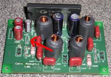
The spot I earthed the shield is inside the red ring. Scratch the laquer away an make an arrangement to attache the wires.
The aluminumtape looks a bit untidy, but I guess it's important to not touch the metal on the tripath chip?
Cheers
Bjorn
An externally hosted image should be here but it was not working when we last tested it.
The aluminumtape looks a bit untidy, but I guess it's important to not touch the metal on the tripath chip?
Cheers
Bjorn
No did not try it on my Amp6 yet, but it looks interesting.
However, I am a bit concerned about your way of shielding the TA2020. The alu foil seems to come awfully close to the pins. Aren't you afraid of shorting it? Besides that, don't you need a little more heatsinking for your chip to stay healthy? Just some concerns for the sake of your music pleasure of course.
However, I am a bit concerned about your way of shielding the TA2020. The alu foil seems to come awfully close to the pins. Aren't you afraid of shorting it? Besides that, don't you need a little more heatsinking for your chip to stay healthy? Just some concerns for the sake of your music pleasure of course.
Hi DocLorren
The tape is far from any pins. I'm planning to switch it with a piece of copper
It's clearly stated that there is no need for cooling the chip. I have tougth about it, but it does not get warm.
For those who is curious on the caps: The input caps on the right is 2,2 uF Obbligato's. The caps on the left is just bunch of different small caps for the railsupply. I run it by SMPS and a battery.
Bjorn
Hi Bjorn,
I agree you do not need heatsinking under low-power conditions; for medium or higher power/low impedance loads though it does not hurt to add a little metal there. You will probably do OK if it does not get warm to the touch in your application. Just be careful when stressing the amp and putting it in a poorly ventilated case.
Btw, what is your source and speakers and did you DIY the Charlize?
Thanks DocLorren
No probs to put on a little coolingfin. Next time I open it up I migth just attach one. There is no ventilation in the box as it is. It's DIY yes.
The Charlize is powering a set of Bastani Prometheus MK2. I run a Cambrige CD to a modified Behringer DCX 2496 (digital input). Trough a 4 channel pot and tube/ss pre. The charlize is filtered from 60 hz and up.
Cheers
Bjorn
No probs to put on a little coolingfin. Next time I open it up I migth just attach one. There is no ventilation in the box as it is. It's DIY yes.
An externally hosted image should be here but it was not working when we last tested it.
The Charlize is powering a set of Bastani Prometheus MK2. I run a Cambrige CD to a modified Behringer DCX 2496 (digital input). Trough a 4 channel pot and tube/ss pre. The charlize is filtered from 60 hz and up.
Cheers
Bjorn
Hi Icebear. Glad you tried the shielding and liked it. The aircore inductors do sound nice, but they are also wonderful little radio transmitters!
And big caps, like the Obbligato and others make wonderful radio receiving antennae. (50/60Hz too). Some caps have metal cases that can be grounded.
My measurements showed that most of the radiation comes from the sides of the coils. When two coils are close together, they really radiate!
What we need to remember with Tripath and other switching amps is that we are not only working with audio signals, but radio frequency signals too. Keeping the signal path and power as clean and free of this RF as possible is good for the overall sound. That's why shielding and good quality power caps can make a difference.
Enjoy your new, better Charlize.
Shield connections
Hi
Best place to tie the inductor shields is the reservoir caps near the power switches. The residual noise currents in the shield want to return to whence they came, eventually. If you tie them to chassis the currents can cause offsets in the signal ground. The inductor shields as shown in the image should be somewhat effective because they are acting as a shorted turn.
icebear said:
Do you recomend shielding the input caps as well?
B
Spacing is best used here. Generally try to keep inputs short (twisted pairs if can't be short) and away from switching and outputs. (looks weird because input caps are so large )
Also output and supply connections usually would benefit with twisted wires as well. Twisted pairs keep the loop area small and balanced for EMI reasons.
infinia said:
Spacing is best used here. Generally try to keep inputs short (twisted pairs if can't be short) and away from switching and outputs. (looks weird because input caps are so large )
Also output and supply connections usually would benefit with twisted wires as well. Twisted pairs keep the loop area small and balanced for EMI reasons.
Would it be benificial to have a smaller input cap? I have some Black Gate 2,2uF laying around, which would fit on the PCB like the old ones.
I'll also change the cabling for some twisted stuff.
Thanks for all your advice.
Cheers
Bjorn
Thanks Pana,Infinia and Bjorn Finished shielding the chokes and the chip
grounding the shields to all to a common point and then to the Filtercap
as recomended. Things sound smoother and very nice,but it is later and
things always sound better later. I used some old computer cable and
hacked it open to get some braid and foil made some little tubes with
elelctrical tape a bit of braid and foil with a copper wire soldered to the
braid for the drain. Im sure that copper sheet would be a more elegant
solution but this seems to be working just fine.
I think I'll go listen to some music now and have a drink.
Would it be benificial to have a smaller input cap?
I think a smaller cap would def. help the chassis layout. Seems you could get a film cap much smaller with a 63 VDC dielectric rating. IMO would try a 1 uF film type with only 5mm lead spacing. Being a smaller value input cap could change input high pass from say 10Hz to 20Hz. I doubt this change would affect the speakers response in a negative way. Sometimes this might help depending on the speakers. For example, if paired with smaller vented speakers having over excursion with higher sub sonic levels.
I think a smaller cap would def. help the chassis layout. Seems you could get a film cap much smaller with a 63 VDC dielectric rating. IMO would try a 1 uF film type with only 5mm lead spacing. Being a smaller value input cap could change input high pass from say 10Hz to 20Hz. I doubt this change would affect the speakers response in a negative way. Sometimes this might help depending on the speakers. For example, if paired with smaller vented speakers having over excursion with higher sub sonic levels.
- Status
- This old topic is closed. If you want to reopen this topic, contact a moderator using the "Report Post" button.
- Home
- Amplifiers
- Class D
- Shielding the Charlize