Thanks Virpz I look forward to seeing the tutorial. This is my first time modding an amp and there are so many pages in this thread it gets confusing.
Since I removed the R35 and R34 resistors do I have to replace those now? If so does anyone know what they are?
Thanks for the help
Since I removed the R35 and R34 resistors do I have to replace those now? If so does anyone know what they are?
Thanks for the help
Last edited:
Small problem.
Hi guys, good to see people still playing with these. Anyway I might have damaged mine, not sure, thought I'd just post and see if anybody can help me.
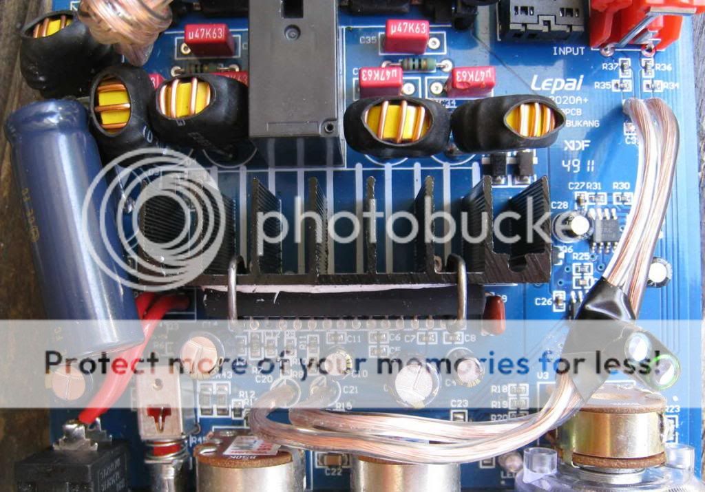
The problem is it does not put any sound out. LOL. But i think i know why, I did a few mods to mine as you can see in the pic. But what happened is, where I bypassed the O.P. amp stage, the 2 wires ended up touching each other just after they come away from the board near the RCA plugs. Anybody know if this could be a course for the TA2020 chip to fail? Or perhaps it can be reset? If anybody in the know could give there opinion i would be greatfull.
P.S. this picture is taken after a rewire.
Hi guys, good to see people still playing with these. Anyway I might have damaged mine, not sure, thought I'd just post and see if anybody can help me.
The problem is it does not put any sound out. LOL. But i think i know why, I did a few mods to mine as you can see in the pic. But what happened is, where I bypassed the O.P. amp stage, the 2 wires ended up touching each other just after they come away from the board near the RCA plugs. Anybody know if this could be a course for the TA2020 chip to fail? Or perhaps it can be reset? If anybody in the know could give there opinion i would be greatfull.
P.S. this picture is taken after a rewire.
An externally hosted image should be here but it was not working when we last tested it.
10,000 uf cap?
Did you calculate that higher value? Others suggest 4700@16v. Thinking about going to 25v for more voltage headroom.Hi my amplifier came today (4th july 2012) and has a red circuit board i have replaced vonage 2a power supply with a xbox 360 16.5a power supply i know its a bit overkill as the thing will only drain about 4-5a and also the 2200uf power cap has been replaced with a much bulkier 10,000uf cap, i am not experiencing the pop when turning on and off and also not experiencing the hiss from the tone controls but my relay isnt engaging when i turn the amplifier up to distortion, i am not sure but could there be a problem with my amplifier?
thanks rob
Hi all,
I just wanted to say thanks to all for this great thread. I've owned a 2020B (in 2020A+ enclosure) for a while now and on the weekend I got up the courage to bypass the tone control and opamp. I used 2.2uF, 63v ROE bipolars. The leads were long enough that I went point to point without needing any wire. The amp sounds much better now. Going to do the output inductors and big power cap at some point.
I just wanted to say thanks to all for this great thread. I've owned a 2020B (in 2020A+ enclosure) for a while now and on the weekend I got up the courage to bypass the tone control and opamp. I used 2.2uF, 63v ROE bipolars. The leads were long enough that I went point to point without needing any wire. The amp sounds much better now. Going to do the output inductors and big power cap at some point.
Hi, I'm looking to get another one of these Lepai amps to mod. I'm wanting to put it in a new enclosure and would like to have the power supply inside the enclosure.
Will a power supply like this work?
12V 5A 60W Switch Switching Power Supply Driver for LED Strip Light Display USA | eBay
Or is there something better out there? For my use, having a power brick external of the amp enclosure will not work.
Will a power supply like this work?
12V 5A 60W Switch Switching Power Supply Driver for LED Strip Light Display USA | eBay
Or is there something better out there? For my use, having a power brick external of the amp enclosure will not work.
Hi, I'm looking to get another one of these Lepai amps to mod. I'm wanting to put it in a new enclosure and would like to have the power supply inside the enclosure.
Will a power supply like this work?
12V 5A 60W Switch Switching Power Supply Driver for LED Strip Light Display USA | eBay
Or is there something better out there? For my use, having a power brick external of the amp enclosure will not work.
Looks perfect, however I am not an authority on this.
Newbie Alert !
Yes, I'm new to the world of Lepai and would like to ask a very basic question as I want to buy one - one of the latest models.
I'm getting confused with the models eg. Lepai TA2020, LP2020, LP2020a, LP2020a+ etc.
Can someone point me to the latest model (I believe it has the anti-pop relay built in) and if anyone can suggest an eBay seller they were happy with that would be a bonus.
Thanks in advance.
JoJo
Thu14feb13
This is what my full plan is to do.Looks perfect, however I am not an authority on this.
Hopefully my poor mspaint drawing is understandable.
An externally hosted image should be here but it was not working when we last tested it.
I've been told by some people that EMI may cause an issue if I dont shield the amp from the raspberry pi and wifi adapter and the power supply.
If you want to correctly bypass and adjust the gain on your lepai then you need to connect directly to the RCA inputs instead of pads on R35 and R34 ( C31 and C 30 on pcb 120305 ) you should know that:
R8 and R10 and the Rin resistors while R9 and R11 are the Rfeed resistors. These are the resistors that adjust the gain. Look into the TA2020 datasheet to get the full explanation.
- For ipod and portable players with built in volume control use 22K for Rin and 39K for Rfeed
- If you want to play it safe with and set your lepai for general use you should use 22K for Rin and 22k for Rfeed.
- For signals coming from a pre-amplifier you can go for 56K for the Rin and 22K for the Rfeed
I will post an definitive mod list for the lepai in a few days . I just need the time to do it correctly with pictures and everything else.
I will also show how to make the "switch" button work as it should; bypassing tone controls for real.
[]'s
Looking forward to the definitive post.
This is what my full plan is to do.
Hopefully my poor mspaint drawing is understandable.

I've been told by some people that EMI may cause an issue if I dont shield the amp from the raspberry pi and wifi adapter and the power supply.
Got my attention here as well.... Looking forward to see how it turns out, do post here when your all done wont you.
Caution
Looks like that item is for 220v and from your flag you're in Canada?
Looks like that item is for 220v and from your flag you're in Canada?
Hi, I'm looking to get another one of these Lepai amps to mod. I'm wanting to put it in a new enclosure and would like to have the power supply inside the enclosure.
Will a power supply like this work?
12V 5A 60W Switch Switching Power Supply Driver for LED Strip Light Display USA | eBay
Or is there something better out there? For my use, having a power brick external of the amp enclosure will not work.
Hi all.
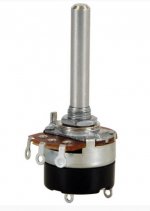
I have a question, hopefully someone can help. I have this amp and want to incorporate the existing on/off toggle and volume functions into a single potentiometer. I have modded several other lepais, but just basically moved the on/off switch to a different spot. I recently bought an on/off volume pot from parts express (see pic) and want to use this. I believe I would run the two power lines into the two leads at the bottom of the pot. The other three would be for the volume. How do I wire those? I assume I'd de-solder the existing volume pot and rewire each of the three leads into the three leads on the new pot? Is it as straightforward as that? Or am I leaving something out? Thank you so much for any help you could recommend. Also, what is the wire soldered to the outside of the volume pot in the circuit board pic earlier in the post? Is that a ground that I would need to solder to the new pot? THANK YOU!
I have a question, hopefully someone can help. I have this amp and want to incorporate the existing on/off toggle and volume functions into a single potentiometer. I have modded several other lepais, but just basically moved the on/off switch to a different spot. I recently bought an on/off volume pot from parts express (see pic) and want to use this. I believe I would run the two power lines into the two leads at the bottom of the pot. The other three would be for the volume. How do I wire those? I assume I'd de-solder the existing volume pot and rewire each of the three leads into the three leads on the new pot? Is it as straightforward as that? Or am I leaving something out? Thank you so much for any help you could recommend. Also, what is the wire soldered to the outside of the volume pot in the circuit board pic earlier in the post? Is that a ground that I would need to solder to the new pot? THANK YOU!
Attachments
If you want to correctly bypass and adjust the gain on your lepai then you need to connect directly to the RCA inputs instead of pads on R35 and R34 ( C31 and C 30 on pcb 120305 ) you should know that:
R8 and R10 and the Rin resistors while R9 and R11 are the Rfeed resistors. These are the resistors that adjust the gain. Look into the TA2020 datasheet to get the full explanation.
- For ipod and portable players with built in volume control use 22K for Rin and 39K for Rfeed
- If you want to play it safe with and set your lepai for general use you should use 22K for Rin and 22k for Rfeed.
- For signals coming from a pre-amplifier you can go for 56K for the Rin and 22K for the Rfeed
I will post an definitive mod list for the lepai in a few days . I just need the time to do it correctly with pictures and everything else.
I will also show how to make the "switch" button work as it should; bypassing tone controls for real.
[]'s
Thanks for sharing this info!
I am wondering if similar/same info is available to do the same thing to the 2020B.
I have successfully bypassed the tone controls and opamp by installing some nice caps as per this post http://www.diyaudio.com/forums/class-d/90500-lepai-t-amp-ta2020-93.html#post2764716
In the future, however, I would like to bypass the volume control and use the 2020B as a power amp, with a DIY tube pre-amp. I am wondering what resistors I need to change (if any) to achieve optimal gain.
Hello everyone,
I got hold of my second 2020A+ amp - 111129 PCB - got it used, not in a best shape, broken volume potentiometer, etc....
here is my ( and its ) problem: when the tone switch is pressed, the right channel goes away - left one is good. I checked the switch, it is fully functional on both positions, and both channels. checked for cold solder, re-soldered a few locations, no difference...
checked the potentiometers, they also good...
when the tone is set to "direct", both channels are fine....
can this be one of the two 4558's on the op-amp?
thanks in advance.
nice, how about adding an USB port in the back or front, for audio storage unit ( usb stick, etc ), or for a RF remote control - I am also curious why are you adding an USB DAC if R-PI has already one built in ( usually it defaults to the HDMI audio, but this can be switched ).
Your project is perfect for getting on-line radio streams, from ShoutCast.for example.
I have done something similar with an ITX board, and re-did GeexBox basically from scratch, than I put all the guts in a vintage ( 1970s ) receiver.enclosure.... still got it")
Good Luck!
Your project is perfect for getting on-line radio streams, from ShoutCast.for example.
I have done something similar with an ITX board, and re-did GeexBox basically from scratch, than I put all the guts in a vintage ( 1970s ) receiver.enclosure.... still got it
Good Luck!
This is what my full plan is to do.
Hopefully my poor mspaint drawing is understandable.
An externally hosted image should be here but it was not working when we last tested it.
I've been told by some people that EMI may cause an issue if I dont shield the amp from the raspberry pi and wifi adapter and the power supply.
Hi all.
I have a question, hopefully someone can help. I have this amp and want to incorporate the existing on/off toggle and volume functions into a single potentiometer. I have modded several other lepais, but just basically moved the on/off switch to a different spot. I recently bought an on/off volume pot from parts express (see pic) and want to use this. I believe I would run the two power lines into the two leads at the bottom of the pot. The other three would be for the volume. How do I wire those? I assume I'd de-solder the existing volume pot and rewire each of the three leads into the three leads on the new pot? Is it as straightforward as that? Or am I leaving something out? Thank you so much for any help you could recommend. Also, what is the wire soldered to the outside of the volume pot in the circuit board pic earlier in the post? Is that a ground that I would need to solder to the new pot? THANK YOU!
Not all three wires I think.
The ones on the outside are generally signal in, if you wire both of them the pot will read max at full and min turn and half it's rating in the centre, I've only wired LED's myself but you only need to connect one side. And which one depends on the direction of the pot you want to low the low resistance. I think.
Please correct me if I'm spouting ****, this is what I've deduced while working with pots and LEDs.
Hello fellow DiY-ers... This is my first post. I've been reading a bunch and I've been learning a ton about these little gems. Thanks to all the contributors.
Currently, I have replaced all my caps with audio grade and changed my inductors. I also removed, cleaned and re-installed my heatsink with better thermal compound.
I am at the point where I want to bypass my tone controls and opamps but i want to keep my volume control.
I understand that I need to run wires from C20 and C21 to C30 and C31 with 2.2uF caps inline to bypass all of this.
I also understand that I need wires from C20 and C21 to the volume pot with 2.2uF cals to enable volume again.
My question is... Do i need a total of 4 wires and 4 caps coming off of C20 and C21 to enable bypass and volume?
Thanks in advance. Anyone have any pictures of this?
I did the last mods on m lepai's lp2020a+. Looking at the output stage noticed that there is a smd cap just after the inductors. Well I have no clue what they intended to anchieve with that cap there but my guess is that it is their EMI output filter and they placed it right there before the output caps. Also the zobel cap on mine had one 0.47uF cap instead of 0.22uF. there we go:
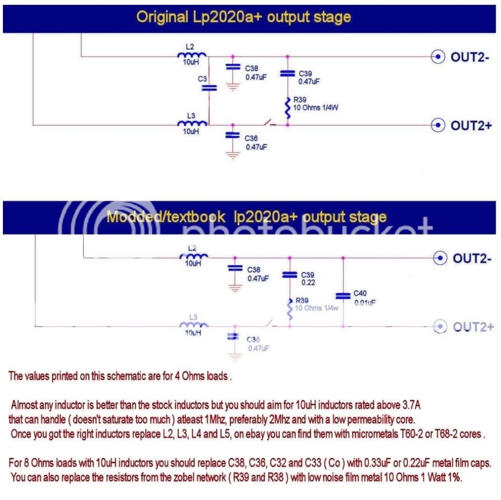
I used 10000pf 5% polystyrenes that I had around for C40 but you can use multilayer ceramics.
If you're going to use it as power amp you better replace R8 and R10 with 22k or 39K low noise resistor. Much better now .
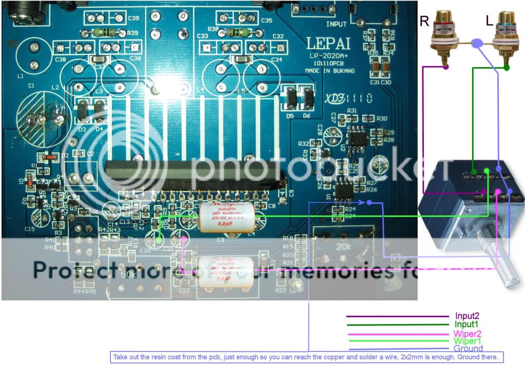
On one of my units I did the bypass and added a volume pot following Pano mod for sonic impact. Great reading there.
If you want add the volume pot after you did the bypass on Lepai Lp2020A+ you should look at the image bellow.
- Status
- This old topic is closed. If you want to reopen this topic, contact a moderator using the "Report Post" button.
- Home
- Amplifiers
- Class D
- Lepai T-Amp with TA2020