Now i have bin reading this for like 2h. My first Lepia broke after a few days and annother is on the way.
My knowledge on all the names and nummers that u guys type is Zero! So i need, as a few of the members requests, is a turtorial. Not just name on stuff u need. We need detaild picture "where" to put "what" on the Lepia. IT whould really help me and some of the others novis here wrry much.
* My first consern is how to NOT make it break after 2 days
* Then how to, easyle, switch some parts to make it work better.
* Make the instruktions simple, so 5 year old can make it.
* Retard as i am, i need pictures, pictures with arrows where to put the part and so on.
I live in Sweden so i rather not have som links to ebay, have no time to wait and to pay for shippment.
I really hope for an awnser on this post, and i hope my limping english works =)
// Gunnar
I would also really appreciate if someone would take the time to point out what needs to be done for the Lapai not to break so easily. My first unit went 'ticking' after a couple of hours.
After reading this thread I understand that the zener diode needs to be removed. Could someone please circle it on a picture of the Lapai?
Thank you in advance!

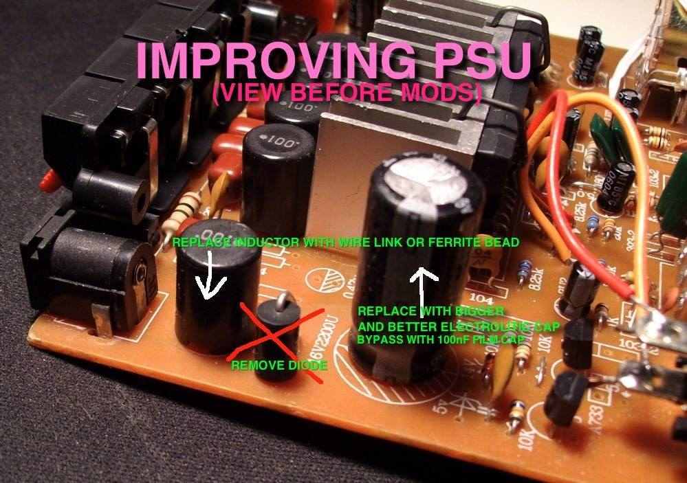
I removed the zener that is marked with "X" on this picture
http://www.diyaudio.com/forums/attachments/class-d/134224d1243379169-lepai-t-amp-ta2020-psu.jpg
it worked after i removed it, then i turnd it off and tried to start it again and nothing....
http://www.diyaudio.com/forums/attachments/class-d/134224d1243379169-lepai-t-amp-ta2020-psu.jpg
it worked after i removed it, then i turnd it off and tried to start it again and nothing....
I removed the zener that is marked with "X" on this picture
http://www.diyaudio.com/forums/attachments/class-d/134224d1243379169-lepai-t-amp-ta2020-psu.jpg
it worked after i removed it, then i turnd it off and tried to start it again and nothing....
That's probably just a reverse polarity protection diode.. ? (someone please correct me if I'm wrong on that) The zener that's been suggested for removal is right in front of the TA2020 chip, in the middle below a ceramic capacitor. It looks like a regular glass diode, and has no text on it (not on mine anyway). From what I understand if a fault condition develops it mutes the amp that leads to the fault condition disappearing the amp starting up again, only to run into the same fault condition again --> oscillate until the chip cooks itself.
Only diode in the middle in front of the IC, can't miss it.
Don't know when I'll open the amp up again to take pictures.
Here's a pic of the removed diode though:
http://img815.imageshack.us/img815/4665/diode.jpg
Don't know when I'll open the amp up again to take pictures.
Here's a pic of the removed diode though:
http://img815.imageshack.us/img815/4665/diode.jpg
I don't have a lepai but mine is one of the small "t" (d) amps and for some reason it hasn't played that loudly since I bought it. Model number is "SA-15". I bought it to use at work to run two 4" woofers with some nice tweeters but now am thinking I probably wouldn't even hear it. (Work on Toyotas) The guy next to me has a cheap boombox that probably has 1w total and plays fairly loud so why won't my amp with twice the rms power play fairly loudly? The two speakers in my car running off the deck blow this thing away in spl.
I'm using:
Zen micro mp3 player or output from my pc
12v/4amp power supply
two 4 ohm 5 1/4"sony car speakers for now
I tried emailing the seller explaining that the gain was way too low and they asked what power supply I was using. 4amps is more than enough to create the rated wattage but it only seems like around 1W a channel.
Any ideas? I've read a lot of this thread but haven't found anything about this yet...
I don't have a lepai but mine is one of the small "t" (d) amps and for some reason it hasn't played that loudly since I bought it. Model number is "SA-15". TA2024 mini Class T Amp Mini HI-FI Stereo Amplifier #1 - eBay (item 270547118593 end time Aug-11-10 14:34:19 PDT) I bought it to use at work to run two 4" woofers with some nice tweeters but now am thinking I probably wouldn't even hear it. (Work on Toyotas) The guy next to me has a cheap boombox that probably has 1w total and plays fairly loud so why won't my amp with twice the rms power play fairly loudly? The two speakers in my car running off the deck blow this thing away in spl.
I'm using:
Zen micro mp3 player or output from my pc
12v/4amp power supply
two 4 ohm 5 1/4"sony car speakers for now
I tried emailing the seller explaining that the gain was way too low and they asked what power supply I was using. 4amps is more than enough to create the rated wattage but it only seems like around 1W a channel.
Any ideas? I've read a lot of this thread but haven't found anything about this yet... Also haven't found a thread about this version but it seems to have the same circuit design but with the 2024 chip instead
Hi,
I just purchased a TA2020 and would like to create a portable speaker. I'd like to use two 6x9's (rated at 50w RMS). Could I get away with using a 12v rechargeable battery pack (8000mah)?
If so, how long do you think it would power the unit?
Any help or advice would be greatly appreciated. Thanks.
I just purchased a TA2020 and would like to create a portable speaker. I'd like to use two 6x9's (rated at 50w RMS). Could I get away with using a 12v rechargeable battery pack (8000mah)?
If so, how long do you think it would power the unit?
Any help or advice would be greatly appreciated. Thanks.
I don't have a lepai but mine is one of the small "t" (d) amps and for some reason it hasn't played that loudly since I bought it. Model number is "SA-15". I bought it to use at work to run two 4" woofers with some nice tweeters but now am thinking I probably wouldn't even hear it. (Work on Toyotas) The guy next to me has a cheap boombox that probably has 1w total and plays fairly loud so why won't my amp with twice the rms power play fairly loudly? The two speakers in my car running off the deck blow this thing away in spl.
I'm using:
Zen micro mp3 player or output from my pc
12v/4amp power supply
two 4 ohm 5 1/4"sony car speakers for now
I tried emailing the seller explaining that the gain was way too low and they asked what power supply I was using. 4amps is more than enough to create the rated wattage but it only seems like around 1W a channel.
Any ideas? I've read a lot of this thread but haven't found anything about this yet...
Input impedance mis-match between the MP3 player and amp. Common issue but this isn't the thread for that.
plenty of suggestions for that in the Boominator thread.Hi,
I just purchased a TA2020 and would like to create a portable speaker. I'd like to use two 6x9's (rated at 50w RMS). Could I get away with using a 12v rechargeable battery pack (8000mah)?
If so, how long do you think it would power the unit?
Any help or advice would be greatly appreciated. Thanks.
")
http://www.diyaudio.com/forums/class-d/104402-boominator-another-stab-ultimate-party-machine.html
Strange.. I tried undoing the factory-hack circled in red here: http://img651.imageshack.us/img651/9361/lepaiwut.jpg
And I get some hissing noise on bass test tracks.
It's completely gone if it's connected like this though.
And I get some hissing noise on bass test tracks.
It's completely gone if it's connected like this though.
Input impedance mis-match between the MP3 player and amp. Common issue but this isn't the thread for that.
Sucks the ad says you can use your mp3 player with it. Also claims 200mv for rated output. Maybe the seller doesn't understand quite how to use them? Would you be so kind as to point me to the thread for this?
mods summary
Just got mine a few days ago and now I'm ready to do some mods.
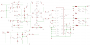
Before I started, I drew a schematic of the version I have (lp2020sch.png) to help me understand the circuit better. The values for some of the components are a bit different from what djnemesi posted on page 45.
From what's been posted so far, I've come up with the following list of mods I'd like to implement:
Safety
1.1. Remove diode between pin 18 and 11 (It's D2 in lp2020sch.png)
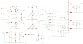
1.2. Add overshoot protection diodes (D2, D7, D9 and D10 in lp2020mods.png)
Input
2.1. Replace input decoupling caps with 2.2uF polypropylenes (C4 & C5)
2.2. Ground the volume pot casing (humming)
2.3. Replace volume pot with log 100K pot (original pot is a bit scratchy on mine)
2.4. Replace power filter cap (C32) with 4700uF 16/25V
2.5. Flip the "MP3" input channels
Opamp
3.1. Replace JRC4558 with NE5532
3.2. Replace R2, R3, R6, R7, R8 and R9 with 1% resistors (balance that weird left-right dc offset maybe?)
3.3. Add 0.1uF filter cap between pin 1 and 8 (C37 in lp2020mods.png)
Tone control
4.1. Replace C29 and C34 with 1nF MKT
4.2. Replace C28 and C33 with 10nF MKT
4.3. Replace C26 and C30 with 5.6nF MKT
4.4. Replace C27 and C31 with 56nF MKT
4.5. Replace R18 and R21 with wire
4.6. Replace R17 and R22 with 10K 1%
4.7. Replace R15 and R19 with 20K 1%
4.8. Replace R16 and R20 with 2.2K 1%
4.9. Replace pots with log 100K pots
Fix dc offset
5.1. Add the trimming circuit to pin 10 and 13 (see lp2020mods.png)
Output
6.1. Replace output inductors with 10uH 3A toroids
Extras
7.1. Add LED and resistor to fault pin 18
7.2. Add the pop suppressor circuit (see lp2020mods.png)
7.3. Replace the rest of the decoupling caps (C2, C3, C9, and C10) with 2.2uF MKT
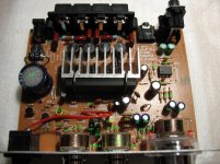
If you don't feel like tracing where some of these parts are located physically, I've labeled them on lp2020-top.jpg.
A couple of other things I notice that might be of help:
There seems to be a confusion of what part needs to be removed to prevent the ticking death of these amps. There are two parts that looks similar on the board. One is a 14v zener and the other is a 1n4148 switching diode. It's the diode that needs to be removed not the zener. The zener is part of the over voltage protection circuit, you shouldn't remove that.
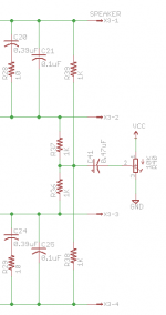
The unpopulated part of the circuit appears to be their attempt at dc offset trimming right at the speaker output pins (see origdcoffset.png). Given that I've got dc offset of 80mV on the left and 100mV on the right, I opted for the two trimmers on the input side rather than to use this part of the board. The other part of this circuit I don't like is the fact that it uses the supply voltage before the power switch so it will always be on even when the amp is off. If I can get the offset to match up with item #3.2, I might try populating this circuit and reroute the supply line to the switched side.
Did I miss any other mods? It's hard to go through 60 pages and not miss anything.
Just got mine a few days ago and now I'm ready to do some mods.
Before I started, I drew a schematic of the version I have (lp2020sch.png) to help me understand the circuit better. The values for some of the components are a bit different from what djnemesi posted on page 45.
From what's been posted so far, I've come up with the following list of mods I'd like to implement:
Safety
1.1. Remove diode between pin 18 and 11 (It's D2 in lp2020sch.png)
1.2. Add overshoot protection diodes (D2, D7, D9 and D10 in lp2020mods.png)
Input
2.1. Replace input decoupling caps with 2.2uF polypropylenes (C4 & C5)
2.2. Ground the volume pot casing (humming)
2.3. Replace volume pot with log 100K pot (original pot is a bit scratchy on mine)
2.4. Replace power filter cap (C32) with 4700uF 16/25V
2.5. Flip the "MP3" input channels
Opamp
3.1. Replace JRC4558 with NE5532
3.2. Replace R2, R3, R6, R7, R8 and R9 with 1% resistors (balance that weird left-right dc offset maybe?)
3.3. Add 0.1uF filter cap between pin 1 and 8 (C37 in lp2020mods.png)
Tone control
4.1. Replace C29 and C34 with 1nF MKT
4.2. Replace C28 and C33 with 10nF MKT
4.3. Replace C26 and C30 with 5.6nF MKT
4.4. Replace C27 and C31 with 56nF MKT
4.5. Replace R18 and R21 with wire
4.6. Replace R17 and R22 with 10K 1%
4.7. Replace R15 and R19 with 20K 1%
4.8. Replace R16 and R20 with 2.2K 1%
4.9. Replace pots with log 100K pots
Fix dc offset
5.1. Add the trimming circuit to pin 10 and 13 (see lp2020mods.png)
Output
6.1. Replace output inductors with 10uH 3A toroids
Extras
7.1. Add LED and resistor to fault pin 18
7.2. Add the pop suppressor circuit (see lp2020mods.png)
7.3. Replace the rest of the decoupling caps (C2, C3, C9, and C10) with 2.2uF MKT
If you don't feel like tracing where some of these parts are located physically, I've labeled them on lp2020-top.jpg.
A couple of other things I notice that might be of help:
There seems to be a confusion of what part needs to be removed to prevent the ticking death of these amps. There are two parts that looks similar on the board. One is a 14v zener and the other is a 1n4148 switching diode. It's the diode that needs to be removed not the zener. The zener is part of the over voltage protection circuit, you shouldn't remove that.
The unpopulated part of the circuit appears to be their attempt at dc offset trimming right at the speaker output pins (see origdcoffset.png). Given that I've got dc offset of 80mV on the left and 100mV on the right, I opted for the two trimmers on the input side rather than to use this part of the board. The other part of this circuit I don't like is the fact that it uses the supply voltage before the power switch so it will always be on even when the amp is off. If I can get the offset to match up with item #3.2, I might try populating this circuit and reroute the supply line to the switched side.
Did I miss any other mods? It's hard to go through 60 pages and not miss anything.
Attachments
I am not sure if I am being retarded or something, but I am unable to solve the hum on the volume knob. I see that you are supposed to ground the pot, so from what I had seen elsewhere, all you had to do was solder a wire from the volume to the bass pot. However, this does not solve it. Do I need to solder directly to the lug? And if so, where do I solder that wire to? Aka, From lug to where?
Thanks.
Thanks.
Check your input and power supply too. Try this: plug a headphone to that "MP3" jack, don't turn on the amp, turn on your input source but don't play it. If you hear the hum in the headphone, try disconnecting the amp's power. If it stops, it's probably coming through the ground side of the power supply. If it's still humming, then it's coming through the input.
- Status
- This old topic is closed. If you want to reopen this topic, contact a moderator using the "Report Post" button.
- Home
- Amplifiers
- Class D
- Lepai T-Amp with TA2020