I'm expecting a Lepai TA2020 in about a week & was invesitigating mods. Are there further mods in addition to Dr lex's ones? Can anyone give a link to the dc offset correction mod schematic? I have some 10uh toroid inductors which I intend to try - is this the correct value?
10uH is the correct value, if the toroids can handle 3A then they're right.
Here's the DC offset correction for one channel: http://www.diyaudio.com/forums/showpost.php?p=1888645&postcount=465
For the other channel, use pins 12, 13 instead of 9, 10.
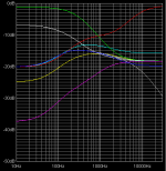
Either bypassing the tone control section or correcting it is also highly recommended. As djnemesi and col already figured out, the tone control is a 'James' Baxandall variation. From simulations it appears the component values that are installed as well as the ones printed on the PCB, are both horrible. With both controls set to neutral, the frequency response is nowhere near flat, it has a huge bump in the midtones. And to top it off, the components are cheap and inaccurate.
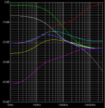
The first attached image shows the responses for bass/treble controls set to 0, 2.5, 5 (flat), 7.5 and 10 for the values that are installed. The curves correspond reasonably to what I measured when taking some extra loss of bass into account. The second image shows curves for the printed values, not much better.
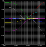
I would suggest the following replacement values (component numbers as on the webpage). This will give the much more balanced characteristics from the third image. As soon as I have the right components, I'm definitely going to do this fix:
R1 (installed 10k, marked 15k): 20k
R3 (installed 1k5, marked 1k): 2k2
R4 (installed 1k, marked 1k5): 10k
C1 (installed 10n, marked 472): 5.6n
C2 (installed 47n, marked 393): 56n
C3 (installed and marked 10n/103 near bass pot): 1n
C4 (installed and marked 10n/103 near treble pot): 10n
There is an additional resistor not in the original James schematic at the treble potmeter (installed somewhere around 300Ω, marked 100). What this one does, is for some reason preventing that the treble control can be set all the way to 0% or 100%. It can be safely replaced by wire links or by any other small value (the marked 100Ω is OK).
Use metal film resistors and your preferred type of film capacitors. Even for C4 which stays the same value you should remove the existing components and replace them by something of higher quality. You can also replace the potmeters although for my needs they are acceptable.
Attachments
DrLex, well done thats awesome!
I will have another go at the tone controls and implement the DC offset circuit when I get the chance.
I also want to replace the volume control with a stepped attenuator that I got off Ebay, It is the same size so should be a drop in replacement.
http://cgi.ebay.com.au/DACT-Type-21...in_0?hash=item1c0c19cba5&_trksid=p3911.c0.m14
col.
Hello Drlex")
just a small Q's regarding the R & C that you put. As a newbie on elctronics do I need to change 2 pairs of the value that you mention?example R1=20k.there is one another beside of it, do i need to change that too? and One more thing on the input resistor between 2.2uf pin 9,10 do it really need to change it to 20k as marked on the pcb is 8.25 something?
Thanks,
Ann
10uH is the correct value, if the toroids can handle 3A then they're right.
Here's the DC offset correction for one channel: http://www.diyaudio.com/forums/showpost.php?p=1888645&postcount=465
For the other channel, use pins 12, 13 instead of 9, 10.
Either bypassing the tone control section or correcting it is also highly recommended. As djnemesi and col already figured out, the tone control is a 'James' Baxandall variation. From simulations it appears the component values that are installed as well as the ones printed on the PCB, are both horrible. With both controls set to neutral, the frequency response is nowhere near flat, it has a huge bump in the midtones. And to top it off, the components are cheap and inaccurate.
The first attached image shows the responses for bass/treble controls set to 0, 2.5, 5 (flat), 7.5 and 10 for the values that are installed. The curves correspond reasonably to what I measured when taking some extra loss of bass into account. The second image shows curves for the printed values, not much better.
I would suggest the following replacement values (component numbers as on the webpage). This will give the much more balanced characteristics from the third image. As soon as I have the right components, I'm definitely going to do this fix:
R1 (installed 10k, marked 15k): 20k
R3 (installed 1k5, marked 1k): 2k2
R4 (installed 1k, marked 1k5): 10k
C1 (installed 10n, marked 472): 5.6n
C2 (installed 47n, marked 393): 56n
C3 (installed and marked 10n/103 near bass pot): 1n
C4 (installed and marked 10n/103 near treble pot): 10n
There is an additional resistor not in the original James schematic at the treble potmeter (installed somewhere around 300Ω, marked 100). What this one does, is for some reason preventing that the treble control can be set all the way to 0% or 100%. It can be safely replaced by wire links or by any other small value (the marked 100Ω is OK).
Use metal film resistors and your preferred type of film capacitors. Even for C4 which stays the same value you should remove the existing components and replace them by something of higher quality. You can also replace the potmeters although for my needs they are acceptable.
Last edited:
Yes, of course there are two pairs for each value, after all it's stereo. I have borrowed one of col's photos to indicate the positions of all components. I haven't checked which exactly belong to the left and right channel, so the 'a' and 'b' components don't necessarily correspond. R7 is the extra resistor at the treble control. As you can see, the 8.25 resistor is not part of the tone circuit.just a small Q's regarding the R & C that you put. As a newbie on elctronics do I need to change 2 pairs of the value that you mention?example R1=20k.there is one another beside of it, do i need to change that too? and One more thing on the input resistor between 2.2uf pin 9,10 do it really need to change it to 20k as marked on the pcb is 8.25 something?
Thanks,
Ann
Attachments

Thanks Drlex
Drlex,
Can we eliminate the pop noise on this amp?
Drlex,
Can we eliminate the pop noise on this amp?
Yes, of course there are two pairs for each value, after all it's stereo. I have borrowed one of col's photos to indicate the positions of all components. I haven't checked which exactly belong to the left and right channel, so the 'a' and 'b' components don't necessarily correspond. R7 is the extra resistor at the treble control. As you can see, the 8.25 resistor is not part of the tone circuit.
Last edited:
The first thing you should do to reduce the pop is implement the DC bias correction and trim the outputs so they are near 0mV. Otherwise there will always be a pop no matter what you do. Next, there are a few options:Drlex,
Can we eliminate the pop noise on this amp?
- Add a 'mute' switch like I did, which toggles pin 17 between the 5V reference (pin 8) and ground. Pin 17 is the 'sleep' pin, alternatively you could use pin 11 which is the 'mute' pin. I don't know which one works best. Set this switch to 5V when powering on the amp, and flip it a few seconds after. It still gives a pop, but it's very acceptable and doesn't make the speaker cones wiggle back and forth. And it allows to mute the amp without touching the volume knob.
- Automate the above by replacing the manual switch with a timer circuit. Look in this older post for a possible circuit.
- Add a relay which physically disconnects the speaker terminals until a few seconds after powering on the amp. This will completely eliminate the pop, but may be tricky to solder. You will need to break traces and find space for the relays.
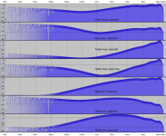
All right, the capacitors for the tone circuit and the toroids arrived yesterday. I first did the tone circuit and repeated my "poor man's frequency response test". The curves look much better now, and approximate the ones from the simulator. And of course it sounds a whole lot better. As you can see, with the controls 'flat' (i.e. both knobs centered), there is already a bass and treble boost. To get the response really flat I need to turn the knobs more to the left. The reason is that the built-in potmeters aren't logarithmic . They appear to have some weird sigmoid-like characteristic.
After this I replaced the ridiculously small inductors with the toroids, and repeated the experiment. But there was no effect on the curves, they look identical. I guess this is because I had to set the volume very low to avoid oversteering the line-in of the recorder. At such low volume the currents are small and the crappy built-in coils probably don't cause much degradation yet. So the only test I could do is hook up some speakers and crank the volume, and it certainly sounds great.
While I was experimenting anyway, I did some tests with bypassing the entire opamp/tone section and only the tone controls. The good news is: the frequency response is perfectly flat in both cases. That is, of course, after all my hacks, so I can't tell what it would have been with the standard components.
I first did the tone circuit and repeated my "poor man's frequency response test". The curves look much better now, and approximate the ones from the simulator. And of course it sounds a whole lot better. As you can see, with the controls 'flat' (i.e. both knobs centered), there is already a bass and treble boost. To get the response really flat I need to turn the knobs more to the left. The reason is that the built-in potmeters aren't logarithmic . They appear to have some weird sigmoid-like characteristic.After this I replaced the ridiculously small inductors with the toroids, and repeated the experiment. But there was no effect on the curves, they look identical. I guess this is because I had to set the volume very low to avoid oversteering the line-in of the recorder. At such low volume the currents are small and the crappy built-in coils probably don't cause much degradation yet. So the only test I could do is hook up some speakers and crank the volume, and it certainly sounds great.
While I was experimenting anyway, I did some tests with bypassing the entire opamp/tone section and only the tone controls. The good news is: the frequency response is perfectly flat in both cases. That is, of course, after all my hacks, so I can't tell what it would have been with the standard components.
Attachments
All right, the capacitors for the tone circuit and the toroids arrived yesterday.
After this I replaced the ridiculously small inductors with the toroids, and repeated the experiment. But there was no effect on the curves, they look identical. I guess this is because I had to set the volume very low to avoid oversteering the line-in of the recorder. At such low volume the currents are small and the crappy built-in coils probably don't cause much degradation yet. So the only test I could do is hook up some speakers and crank the volume, and it certainly sounds great.
While I was experimenting anyway, I did some tests with bypassing the entire opamp/tone section and only the tone controls. The good news is: the frequency response is perfectly flat in both cases. That is, of course, after all my hacks, so I can't tell what it would have been with the standard components.
Hi DrLex,
Would you please change the capacitor as mentioned in the post no#258? The sound quality is much better. Can you test with your equiment? Thank you.
Hello Masters,
Just wanna ask how to check the dc bias on my lepai. I measure the voltage of both speaker connection but what I get is 3 - 0mv. Is this one?
Thanks,
Ann
You should switch on the amp, wait a minute until it stabilizes, and connect a voltmeter to the red and black socket of each speaker terminal. It is possible that you're lucky and that your amp has nearly no bias, but mine had more than 120mV on one channel and about 60mV on the other. If you correctly trim the DC bias, you should hear nothing when you connect speakers while the amp is powered on. Otherwise you'll hear crackling sounds.
I doubt whether this will show any visible difference in the curves, due to the same reason I gave in my previous post. I could try to attenuate the line-in with a potmeter so I can crank the volume, but even then I can only give the amp a 5W load because that's as far as my resistors will go. I may do the test when I have better resistors and the correct capacitor, but that could take a while...Hi DrLex,
Would you please change the capacitor as mentioned in the post no#258? The sound quality is much better. Can you test with your equiment? Thank you.
I could also hook up some speakers of course, but playing that constant amplitude sweep up to the highest frequencies at maximum volume will probably damage both my ears and speakers and make all the dogs in the neighborhood go crazy burn it
Hello,
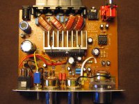
I bought a LEPAI TA2020, but when I connected in to the power supply 12vdc 10A, my Lepai broke.
I opened it and I saw that an inductor burned, please, look at the photo.
I have to replace it, wich inductor or coil (i don't know) i have to put it (specs).
Thanks
Dj_vini
Hello,
I bought a LEPAI TA2020, but when I connected in to the power supply 12vdc 10A, my Lepai broke.
I opened it and I saw that an inductor burned, please, look at the photo.
I have to replace it, wich inductor or coil (i don't know) i have to put it (specs).
Thanks
Dj_vini
Attachments
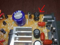
Hi dj_vini are you sure that you have your supply the right way round. The diode next to the inductor will short the supply if it is the wrong polarity and cause the inductor to burn. The inductor is probably the same as the others on the board ie 10uH. It needs to be able to carry the full supply current about 4-5 amps.
Tony
Tony
I got my Lepai & bypassed all the input circuitry including the 3.3uF (?) input capacitor by using a transformer input - one end of secondary winding connected to input & the other end connected to pin 14 Biascap. So no capacitors in the signal path - sounds wonderful (I'm feeding it directly from a PCM1793 differential Vout DAC - the primary is handling the 1.4V bias on each differential output leg)
I've changed the Ri & Rf resistors both to 20K metal & changed the output inductors to 10uH toroids that I had around for my SI amp.
I didn't change the 0.47uF output caps (Co in the datasheet) yet - are the stock ones low quality? Does this make much of a difference? I haven't changed the Zobel 0.47uF cap either - same question again. Should this be 0.47 or 0.22uf as in the datasheet? Same for the Cdo differential 0.01uF cap.
(I'm feeding it directly from a PCM1793 differential Vout DAC - the primary is handling the 1.4V bias on each differential output leg)I've changed the Ri & Rf resistors both to 20K metal & changed the output inductors to 10uH toroids that I had around for my SI amp.
I didn't change the 0.47uF output caps (Co in the datasheet) yet - are the stock ones low quality? Does this make much of a difference? I haven't changed the Zobel 0.47uF cap either - same question again. Should this be 0.47 or 0.22uf as in the datasheet? Same for the Cdo differential 0.01uF cap.
- Status
- This old topic is closed. If you want to reopen this topic, contact a moderator using the "Report Post" button.
- Home
- Amplifiers
- Class D
- Lepai T-Amp with TA2020