I have received 3 new 2020A+ from ebay.
They have the new PCB (red one version 120301) I guess version number on pcb is YearMonthDay of pcb design.(same as post #1203)
I have some small plop sound with this amp : - small pop when relay commutes 2 seconds after powering on.
- bigger pop when switching off.
But it seems reasonable level and should not make any damage to my speaker.
2 of my boards are not working well : sometimes sound level is dropping. I have noticed that pushing on PCB make it happens easily. I feel it is soldering issue on some components. After checking last year posts, it seems no one has posted any schematics of 2020A+ version. Anyone has something that could be shared ? (I just found the naked pcb in Viprz post #935)
thanks
Looks like subsonic bass, severe turntable rumble can do this.
Does anyone have a good psu schematic for this amp? I will get mine tomorrow from the postal office and would like to build a psu for it. I also have a PSU from a computer, could I use the 12V from it? I know I could just buy a laptop style psu but it'd be nice if I built it as I could learn some on the way.
Yep, my video.
Looks like subsonic bass, severe turntable rumble can do this.
They're bass tests. I have two videos up there, Wharfedale Diamond 10.2 Bass Response #1 and #2, other song has "Opus Dei Bass Test" song used, other song is "Bassotronics - Bass I love You"
I have two other speaker videos up there as well in which I used TA2020A+ amp, speakers in those videos are old GenExxa GX1000 floorstanders from 80's iirc.
Last edited:
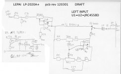
I have started the schematics based on my amp and the picture already posted by Viprz. Very helpful.
The input part, including EQ and preamp is ready. I don't have time to make it clean schematics, if someone has some schematics tool, feel free to copy.
I am not 100% sure that I have not mixed some parts... Seems that ref are matching with Viprz pcb, even if some have moved.
In fact, it is quite interesting, input has been totally redesigned on this PCB. It is clear that 2020 and 2020A+ will sound totally different.
Some comments :
1) Both JRC are powered through Q6. I am not sure of the purpose of this, I have nearly the same voltage on Ic supply and main. any idea ? (Kind of soft start)
2) There is 2 amplification stage : one for main volume, and one for EQ. U2 is for main volume, U1 is for EQ.
3) The "EQ bypass" bypass U1 and the EQ part, and shorten audio path.
4) the volume potentiometer have no pin connected to ground : potentiometer is part of the feedback loop of U2. It make a "long" feedback loop
I have not checked the other parts, but I will attach my first part of the puzzle. Hope it will help.
ihbar
Attachments
How can it be be bass tests if you cannot hear it. I tried to listen to your youtube offering through 15 inch drivers and there was not a sound when the cone was flapping around.Yep, my video.
They're bass tests. I have two videos up there, Wharfedale Diamond 10.2 Bass Response #1 and #2, other song has "Opus Dei Bass Test" song used, other song is "Bassotronics - Bass I love You"
I have two other speaker videos up there as well in which I used TA2020A+ amp, speakers in those videos are old GenExxa GX1000 floorstanders from 80's iirc.
How can it be be bass tests if you cannot hear it. I tried to listen to your youtube offering through 15 inch drivers and there was not a sound when the cone was flapping around.

I'm not sure if you're serious...
Maybe you should listen to the ORIGINAL song instead of a RECORDING done with a phone..
Bass Test - Opus Dei - YouTube
Bassotronics - Bass, I Love You - YouTube
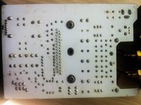
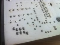
My MUSE M20 EX TA2020 amp just arrived. I opened it and looks nice and clean. I like the quality of the build. It is compact and very solid. Haven't got a chance to test it yet as I need a psu but will do in the next days. I only opened it to check the insides. My only problem is with the soldering, doesn't seem to be really good, some pins are not completely covered in solder. I will have to touch most of them when I'll be making some upgrades to it. Right now I wonder what would the PSU cap be so I can exchange for a larger one. The inductors seem sturdy but I'll replace those as well. What does the 100 on them mean?
Attachments
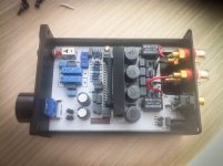
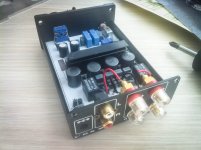
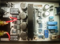
The ebay description says that the inductors are Toko fixed inductors. the 100 mark means 10uH so I traced to this datasheet:
A7503AY-100M datasheet(1/1 Pages) TOKO | Fixed Inductors for Digital Audio Amplifier
model A7503AY-100M shielded
But not sure on that. Should I change them with toroidal type? The datasheet rates it for 4.32A.
Also which one is the power cap that is recommended to be changed to at least 4700uF/16V ? The small golden one? I'm asking here since the schematic must be real similar to the Lepai amp.
***later edit***
I found a Cisco Router psu that is rated 12V at 5A and connector fits perfect.
A7503AY-100M datasheet(1/1 Pages) TOKO | Fixed Inductors for Digital Audio Amplifier
model A7503AY-100M shielded
But not sure on that. Should I change them with toroidal type? The datasheet rates it for 4.32A.
Also which one is the power cap that is recommended to be changed to at least 4700uF/16V ? The small golden one? I'm asking here since the schematic must be real similar to the Lepai amp.
***later edit***
I found a Cisco Router psu that is rated 12V at 5A
and connector fits perfect.Been 'reviewing' my latest version Lepai.
It is good, especially so considering it's 12 pack Beer pricings .
Likely even a bit better with new inductors etc .. I'm genuinely hoping.
'Wonderful' is perhaps stretching it a wee bit too far though.
Perfect gizmo for a secondary/tertiary system.
No interest whatsoever in what others hear or claim to.
Been doing this for wayyy too many years to give credence or even time to 'reviews'
It is good, especially so considering it's 12 pack Beer pricings .
Likely even a bit better with new inductors etc .. I'm genuinely hoping
.'Wonderful' is perhaps stretching it a wee bit too far though.
Perfect gizmo for a secondary/tertiary system.
No interest whatsoever in what others hear or claim to.
Been doing this for wayyy too many years to give credence or even time to 'reviews'
Is this Habey PW-12V402 12V 5A DC power supply compatible with the Lepai amp?
Newegg.ca - Habey PW-12V402 12V 5A DC Power Supply Adapter with Power Cord UL certified - Server Accessories
Newegg.ca - Habey PW-12V402 12V 5A DC Power Supply Adapter with Power Cord UL certified - Server Accessories
Is this Habey PW-12V402 12V 5A DC power supply compatible with the Lepai amp?
Newegg.ca - Habey PW-12V402 12V 5A DC Power Supply Adapter with Power Cord UL certified - Server Accessories
I'm using something similar and it works very good but I am waiting on a 13.5V supply to test. As others on this topic recommend I'd say get a 13-13.5V one.
I bought this one.. it works "fine':
12V 5A LCD Replacement AC Adapter for DVE DSA-60W-12 1 | eBay
Although there was a problem with the supplied AC cable's plug (mfg error).
Fortunately everybody has a few spares
12V 5A LCD Replacement AC Adapter for DVE DSA-60W-12 1 | eBay
Although there was a problem with the supplied AC cable's plug (mfg error).
Fortunately everybody has a few spares
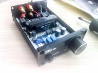
Did Several Mods today to my red PCB Lepai:
Good quality (yellow rectangle) output caps replacing the 047 blue ceramic output ones. Also a pair of 2.2 Film /foils replacing C20/21
Stock inductors .. still
ALL new better quality Caps, 4700/16v on PS as well as a bypass for it.
Have not yet touched the op amps or deleting the tone assemblies/circuits, wanting to get to know the thing modded Before deleting all that stuff.
Tone controls work, not impressively well, but they do work. Likely they will be removed.
Sound is good, Bass is decently deep and sharp when it's needs be.
No problems there.
Driving 8"full rangers . Volume is to genuine ear hurting levels and no clipping.
These are Old (early 70's) efficient and very pleasing drivers.. which is why I've hung onto to these things for 40 years.
Problem though. I tripped over the left speaker wire ripping it out of the cheesy lepai speaker clips. BUT now the thing is ONLY running on right channel. Left is Dead.. period
Have pulled off and refitted ALL the plug bits on the rear of the PCB.
Reflowed ALL the solder connections.. Still on right channel only. Grrr.
Shorting (finger tip) the 2020 chips' solder blobs on the underside of the board I can produce a large hum from either channel/speaker.
So Signal is seemingly going out.. I think?
I have a spare Ta 2020 chip,
But am thinking that the problem may not be the chip itself.. Any ideas?
Good quality (yellow rectangle) output caps replacing the 047 blue ceramic output ones. Also a pair of 2.2 Film /foils replacing C20/21
Stock inductors .. still
ALL new better quality Caps, 4700/16v on PS as well as a bypass for it.
Have not yet touched the op amps or deleting the tone assemblies/circuits, wanting to get to know the thing modded Before deleting all that stuff.
Tone controls work, not impressively well, but they do work. Likely they will be removed.
Sound is good, Bass is decently deep and sharp when it's needs be
.No problems there.
Driving 8"full rangers . Volume is to genuine ear hurting levels and no clipping.
These are Old (early 70's) efficient and very pleasing drivers.. which is why I've hung onto to these things for 40 years
.Problem though. I tripped over the left speaker wire ripping it out of the cheesy lepai speaker clips. BUT now the thing is ONLY running on right channel. Left is Dead.. period
Have pulled off and refitted ALL the plug bits on the rear of the PCB.
Reflowed ALL the solder connections.. Still on right channel only. Grrr.
Shorting (finger tip) the 2020 chips' solder blobs on the underside of the board I can produce a large hum from either channel/speaker.
So Signal is seemingly going out.. I think?
I have a spare Ta 2020 chip,
But am thinking that the problem may not be the chip itself.. Any ideas?
What about this Meawell AC adapter?
GS40A12-P1J, Mean Well GS40A12-P1J
GS40A12-P1J, Mean Well GS40A12-P1J
What about this Meawell AC adapter?
GS40A12-P1J, Mean Well GS40A12-P1J
This looks a better deal
MUSE 14V 4A Power Adapter Supply for Muse M20 EX2 TA2020 M21 EX TA2021 T-Amp | eBay
Hi there,
Just make sure the Muse power supply is in fact 14V. Can't recall which seller I bought from, but the Muse power supply was actually only 12V even though it was advertised as 14V. My advice is to double check with the seller and also measure if if you end up purchasing.
Cheers,
Pete
Just make sure the Muse power supply is in fact 14V. Can't recall which seller I bought from, but the Muse power supply was actually only 12V even though it was advertised as 14V. My advice is to double check with the seller and also measure if if you end up purchasing.
Cheers,
Pete
Hi there,
Just make sure the Muse power supply is in fact 14V. Can't recall which seller I bought from, but the Muse power supply was actually only 12V even though it was advertised as 14V. My advice is to double check with the seller and also measure if if you end up purchasing.
Cheers,
Pete
The Muse power supply I received last week measured 14v.
Even it it only tested 12v it is still a very good buy, I would not have been too dissappointed.
I really do not notice the difference between my original 12v 2amp ps and the Muse 14v 4amp, but I am connected to some huge, efficient speakers
The Muse power supply I received last week measured 14v.
Even it it only tested 12v it is still a very good buy, I would not have been too dissappointed.
I really do not notice the difference between my original 12v 2amp ps and the Muse 14v 4amp, but I am connected to some huge, efficient speakers
You mean you couldn't tell the difference between the Vonage power supply and the Muse?
Since Mean Well has been recommended as a power supply in general, I thought it would make a difference.
- Status
- This old topic is closed. If you want to reopen this topic, contact a moderator using the "Report Post" button.
- Home
- Amplifiers
- Class D
- Lepai T-Amp with TA2020