Thanks Cuzin Lee.
No worries about grounding the the chip to the case, my Octopus amps were all like that. Makes a wonderful heatsink.
So I don't know why you had the grounding woes, will have to look into that. For sure you can't ground any of the speaker leads. But power and signal should be no problem. Wonder what happened?
BTW, is the internet killing the use of "earth" in the UK in favor of the US "ground"?
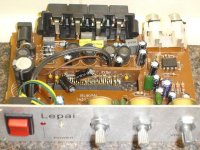
You'll actually got a different revision of the board than the one Panomaniac post pictures of, the same board I have aswell. Your 2200uf cap is position quite a bit further away from the inductor, and the 2 original 100uf power caps have more space around them aswell. The 100uf power cap on the mainboard is the one on mine that shorted.
Thanks for the heads up on the grounding problems, will most definitely save some people some heartache
Thanks for the heads up on the grounding problems, will most definitely save some people some heartache
panomaniac said:BTW, is the internet killing the use of "earth" in the UK in favor of the US "ground"?
As you know Michael, I'm not educated in electrical engineering but I only tend to use 'earth' as safety earth, i.e. connected directly to a water pipe or the UK's 'third' pin.
So your amps have the copper grounded to the case? I always thought that was a no-no?
Not sure why it faulted but I'm also wondering if that PCB is touching the casing where it slots/slides in.......
Zbuff, yes I had noticed that MM's has a wire from the treble pot to ground and that the output caps are orientated a different way... Wonder what else was changed?
Attachments
panomaniac said:I have the other 2.
This is about the junkiest built T-Amp I've seen. And the only one with all thru hole components. Real cheap Chinese stuff. The insides are like a bad trip back to the 70s.
But it does sound pretty good! Surprise, surprise.
The PCB is what is known in the industry as a single sided "unsupported" hole board, this is typically what you will find in alot of DVD player and VCR machines these days. With an unsupported hole board you have to be careful on how through hole components are installed, in the case with Lepai, the traces are on the bottom side which has the danger of delaminating the traces if you put any pressure on the components, the idea method for these boards would have been to install the componets on the trace side, but using a conventional wave to solder the parts, they have to do it this way with the trace on the bottom.
After the holiday period, I've had a little time to have a look a bit closer at the amp and do some listening comparisions to my Sonic Impact. Aside from the bass I like the sound of the SI better, it has a more spatial air sound with better seperation. I'm putting it all down to the complex input section in the Lepai though, it takes up near HALF the board. I thought the Lepai sounded alot less dynamic and duller than the SI at the start, I had both my treble and boss controls set at 12 o'clock then I realised that to make the levels of SI I had to put the treble at 2 o'clock and the bass at 1 o'clock on my amp, quickly confirmed by putting my DMM on the speaker outputs and playing some test tones.
It seems a pretty simple matter to just bypass the whole lot by connecting from the back of the 10uf input caps to the channel inputs onto the PCB where it joins to the standup, the required resistors seem to be on the standup. Haven't done as of yet, it would be nice to retain the BOSS control as suggest by the rest of you but I would imagine the improvement would be quite large from bypassing it all, and would resolve all the deficiencies compared to my SI.
I've been looking at the datashet for th TA2020 and noticed that the Lepai seems to missing the Differential Output Capacitors, are these needed? Might these fix my slight hiss?
I replaced Csw the 100uf caps with some 1000uf caps the same as you did Lee but as of yet haven't put in any .1uf decoupling caps, are MKTs or ceramics better for this usage? It added alot more slam and control in the bass department, I think without the decoupling cap it might have killed my dynamics a little going up to much larger cap size. It also removed all the hum and some of the hiss on the speaker, pretty much removed the DC offset I had on one channel, but unfortunately on the other that I had a problem with before(measures ~150mv) didn't effect it at all. So I'm starting to wonder if my problem resides in the audio input or the speaker output sections now, has anyone got any ideas?
I've had mine go into protection mode too from putting it ontop of ground metal case too just like Lee Those big booms can't be a good thing for speakers. I've gone and put some stick on feet on the base now.
Other differences between your board and Panomaniac's one, a couple of extra resistors on bottom in the powersupply section, an extra bypass ceramic cap where the tank capacitor sits on our boards. Oh how do I go about drill new through holes for that tank capacitor so I can reposition it, how do I make new solderpads for the leads, do I just remove the varnish off the traces?
It seems a pretty simple matter to just bypass the whole lot by connecting from the back of the 10uf input caps to the channel inputs onto the PCB where it joins to the standup, the required resistors seem to be on the standup. Haven't done as of yet, it would be nice to retain the BOSS control as suggest by the rest of you but I would imagine the improvement would be quite large from bypassing it all, and would resolve all the deficiencies compared to my SI.
I've been looking at the datashet for th TA2020 and noticed that the Lepai seems to missing the Differential Output Capacitors, are these needed? Might these fix my slight hiss?
I replaced Csw the 100uf caps with some 1000uf caps the same as you did Lee but as of yet haven't put in any .1uf decoupling caps, are MKTs or ceramics better for this usage? It added alot more slam and control in the bass department, I think without the decoupling cap it might have killed my dynamics a little going up to much larger cap size. It also removed all the hum and some of the hiss on the speaker, pretty much removed the DC offset I had on one channel, but unfortunately on the other that I had a problem with before(measures ~150mv) didn't effect it at all. So I'm starting to wonder if my problem resides in the audio input or the speaker output sections now, has anyone got any ideas?
I've had mine go into protection mode too from putting it ontop of ground metal case too just like Lee
Those big booms can't be a good thing for speakers. I've gone and put some stick on feet on the base now.Other differences between your board and Panomaniac's one, a couple of extra resistors on bottom in the powersupply section, an extra bypass ceramic cap where the tank capacitor sits on our boards. Oh how do I go about drill new through holes for that tank capacitor so I can reposition it, how do I make new solderpads for the leads, do I just remove the varnish off the traces?
zBuff said:I've had mine go into protection mode too from putting it ontop of ground metal case too just like Lee
Pretty disconcerting isn't it!

I found that the PCB connected with the case where it slides in! Wrapped some insulation tape around the edges and the problem has gone away.
Not that I care that much, as you say, the Lepai is too busy on the input with way too much buffering and filtering…I agree...bypass the lot…even the Boss!
Oh and Yes, just gently scrape the varnish off and put a little flux on the trace. Then give it a little solder to tin it before you solder the wires on.
Two more weeks and my new amp will be ready……remote volume is my concern at this moment in time…….
Who's the winner?
So - at this stage of partial modding - is the Lepai not as good as , as good as, or better than the Sonic Impact?
I haven't started modding my S.I. or Lepai yet. In standard form they are quite different and which sounds best depends on the CD player and speakers they are used with.
So - at this stage of partial modding - is the Lepai not as good as , as good as, or better than the Sonic Impact?
I haven't started modding my S.I. or Lepai yet. In standard form they are quite different and which sounds best depends on the CD player and speakers they are used with.
As you mentioned how they'd perform would vary quite a bit depend on input and speakers. The A-B testing I did was only across one set of little bookshelfs (Kef C10s) and having an mp3 player for the input. So I'm guessing the impedence matching would have been better for the Sonic Impact for a starter. When I was away on holiday I did try the Lepai on few different CD player/speaker combinations, it performed very well on some higher sensitivity speakers. Unfortunately I forgot to take my SI with me to do some comparisions. The SI wasn't better in all respects, just in some of the ones that matter the most to me, it sounded more natural to my ears.
I'm pretty confident that once both of them are modded the Lepai will be better in all respects than the SI, mainly due to the fact that I'll be able to make more modifications to the Lepai because of the thru hole construction.
I'm going to bypass all the tone controls tonight actually, so I'll report back later to let you know how it goes.
I initially tried the S.I. with a small pair od JPW bookshelf speakers (87db/W) and a Marantz CD60 (TDA1541A). The JPW's don't produce much bass because of their size but the CD60 has a big and full sound. This seemed to work quite nicely and the lack of bass was not too obvious because everything else sounded so good. There was a real sparkle and ghusto to the sound.
Then I put the Lepai into this system and the difference was huge - mainly in the lower frequencies. The bass response was much better. This must be due to the difference in the size of the input capacitors. However, some of the sparkle and livliness in the upper frequencies was gone. So, I changed the CD player to a Marantz CD65 (also TDA1541 but with a much dryer sound). This seemed to suite the Lepai amp much better and the life returned to the music.
Now I'm trying a larger and more sensitive pair of Jensen bookshelf speakers (93db/w) which emphasize the bass quite a lot. These seem to match very nicely with the S.I. Even in it's unmodded state, it is thumping out some serious bass.
The real test would have to be a comparisson of the Lepai against an S.I. with larger input caps.
YES !!!!
Wow what a difference that made, just finished bypassing all the tone controls. I've currently just got it implemented somewhat makeshiftly, I removed the 3.3uf electrolytics caps behind the overload LED(this marks the end of the tone controls) and unsoldered the inputs caps(I have them replaced with polyester film 2.2uf caps when I first got the amp), then flipped them over to the bottom of the board hooked one leg on the trace from the volume pot then soldered a wire from the other leg to the input solder pads at the base of the upstand(if you're looking at the bottom of the board with the front facing towards you it will the the 2 left most pads). I've done it this way just to test before I go chopping any traces.
Turn on the power, first thing I noticed was hardly any turn on thump compared to before, next the music......
Everything I liked about the SI over the Lepai in my previously listenings was now on the Lepai, plus all the benefits that the Lepai had over the SI. Awesome. Back to some more listening now.
Good work!
I just had a Lepai apart the other day ready to do surgery. Need to get to it.
The signal comes in, goes thru the pot, then the little dual opamp, then over to the tone controls and on to the chip. I guess the opamp is there to make up for the gain loss in the tone controls.
There are several nasty electrolytics in the path along the way, as well as the tone controls and the generic opamp.
Couldn't hurt to clean all that up. Seems like zBuff did and reaped the benefits.
I should be finished with mine next week. Will post what I find.
I just had a Lepai apart the other day ready to do surgery. Need to get to it.
The signal comes in, goes thru the pot, then the little dual opamp, then over to the tone controls and on to the chip. I guess the opamp is there to make up for the gain loss in the tone controls.
There are several nasty electrolytics in the path along the way, as well as the tone controls and the generic opamp.
Couldn't hurt to clean all that up.
Seems like zBuff did and reaped the benefits.I should be finished with mine next week. Will post what I find.
I think I've finally found the cause of my DC offset, one of the .1uf decoupling caps on the standup board that supplies the main powerlines seems to be melted. Can somebody tell me what type of capacitor it is? it's the same as the 2 104 on either side of the speaker output capacitors. Little orange tubular things, around the size of a metallic resistor but fatter and in an axial leg arrangement.
Seems it might be a good idea to take them out anyway and put them closer to the chip pins as Lee did.
Edit : nope removing that cap didn't fix my problem
Seems it might be a good idea to take them out anyway and put them closer to the chip pins as Lee did.
Edit : nope removing that cap didn't fix my problem
I was wrong about removing the 0.1uf caps off the standup, they are decoupling caps for some other powerlines, so leave them in place.
The standup board makes it a bit hard to follow which pins traces connect to.
Who needs to do mazes to stimulate the mind, just try to map out a circuit board
Other improvements I can forsee at the moment? removing the LEDs.
Taking out the inductor on the main power line in if you're using a linear powersupply or a battery perhaps.
NAN40 Power Supply
Hi,
This is my first post here and it's just to say thanks Fin for your recommendation on the NAN40 .
I got 2 and have to say they are axactly as stated.
They put out 13.49v and help my (slightly modded) SI to power fairly inefficient speakers.
Thanks and nice to meet you all
Hi,
This is my first post here and it's just to say thanks Fin for your recommendation on the NAN40 .
I got 2 and have to say they are axactly as stated.
They put out 13.49v and help my (slightly modded) SI to power fairly inefficient speakers.
Thanks and nice to meet you all
OK I've finished mapping out the preamp/tone control section, I'll turn it into something I can upload at some stage, only used old fashioned pen and paper at the moment
I can't make out that much about it at the moment well at least not the tone controls section but sure looks like we'll be able to just bypass the tone controls and retain the advantages of having a preamp
Nice to meet you too Sashmo, always happy to have more company.
Have you checked your heat levels? if you plan on putting up that volume control you might want to have some heatsinking for the chip at that voltage level.
Re: NAN40 Power Supply
Glad to hear that the power supplies worked out well for you. At that price I couldn't resist getting a couple for myself either. They would have to be perfect for this Lepai amp as they put out the exact recommended voltage specified in the datasheet for the TA2020.
As zBuff said.....be carefull using the S.I. with 13.5V. The safe Max for the TA2024 is supposedly 13.2V. I'm happy running mine at 12V just to be safe.
I plan to use two of them, along with two of the Lepai amps, in a bi-amp setup.........whenever I "eventually" get around to it.
zBuff.....you are doing some awesome work there.......
sashmo said:Hi,
This is my first post here and it's just to say thanks Fin for your recommendation on the NAN40 .
I got 2 and have to say they are axactly as stated.
They put out 13.49v and help my (slightly modded) SI to power fairly inefficient speakers.
Thanks and nice to meet you all
Glad to hear that the power supplies worked out well for you. At that price I couldn't resist getting a couple for myself either. They would have to be perfect for this Lepai amp as they put out the exact recommended voltage specified in the datasheet for the TA2020.
As zBuff said.....be carefull using the S.I. with 13.5V. The safe Max for the TA2024 is supposedly 13.2V. I'm happy running mine at 12V just to be safe.
I plan to use two of them, along with two of the Lepai amps, in a bi-amp setup.........whenever I "eventually" get around to it.
zBuff.....you are doing some awesome work there.......
Could someone else test their Lepai and tell me if they're getting any DC offset as well? I've been trying to get rid of it recently I noticed that the Blue LED is fed off the speaker outputs of the left channel, I thought THAT's it, removed the LED and my DC offset actually increased from 150mv to 170mv
Aside from that the Lepai sounds very good with the preamp section bypassed, I'm hearing more midrange and lower bass detail than the stock SI too. And this is me using bookshelfs, the difference would be even more pronounced with speakers capable of a more fullrange reproduction.
Aside from that the Lepai sounds very good with the preamp section bypassed, I'm hearing more midrange and lower bass detail than the stock SI too. And this is me using bookshelfs, the difference would be even more pronounced with speakers capable of a more fullrange reproduction.
- Status
- This old topic is closed. If you want to reopen this topic, contact a moderator using the "Report Post" button.
- Home
- Amplifiers
- Class D
- Lepai T-Amp with TA2020