Hilarious, I have been planning to buy one of these amps on ebay, and I'm surprised you reviewed them so well. Thanks for posting a review. I'm planning to buy one still. I don't mean to hijack your thread, but what kind of speakers did you use with it, and is there anything budget ($45 a pair on parts express) that you'd suggest to use building a small Hifi with?
Hi all
New to posting here, but blown away by various Tripath amps I have.
Have a query, if i may. Others have posted on the strange off switch logic of the Lepai TA2020- doeasn't turn off light, etc. Someone also commented that their case gave hum.
Well, here's my situation. I could angle the amp so it didn't hum, and the off logic was an irritation not an impediment.
And i thought the amp sounded great, and liked the tone controls.
So, I thought - this amp is good - I'll just get my local hifi repair man to fix the hum and switching issue.
Which he has.
But - the amp seems now to have less bass, and what bass there is is terribly controlled.
Is this plausible?
Any thoughts, advice greatly valued.
clicking sound from various speakers with lepai, then lepai making electric wheezing
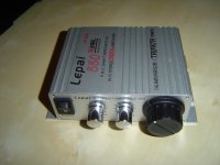
Lepai LP-2020 Class T Stereo Amplifier*
and it worked great for a few hours...then maybe the music was too loud for a second or two because the one of the volume knobs on my computer got turned up, then the music would not play anymore and the speakers have a clicking sound constantly, over and over...i tried hooking up different speakers and the same thing occurs...is my t-amp ruined?
I tried unplugging everything, restarting, and turning the t-amp on and off...
any suggestions?+
why is there a cut in half power plug included?
okay an update.
now the light will not come on in the front of the t-amp. still no sound coming out of speakers connected to it. the light on the adapter plugged into the wall lights up, but there is a weird sound coming from the unit when it is turned on an plugged into the wall. the sound is not coming from the speakers but from the t-amp or from the power adapter connected to the t-amp, it kind of sounds like an electric sucking sound. i looked inside the t-amp and nothing looks burnt or wierd. the t-amp does have a little smell from it, like it got pretty warm. i tried different 12v dc power adapters and the t-=amp would not light up or turn on, but the electronic sucking sound was not there.
I bought this to use with some of the old Radio Shack Realistic Minimus 7 bookshelf speakers. These speakers are 8 ohms with a 40 watt max cat no 40-2045
I also got some klh bookshelfs (I think the came with a subwoofer originally but I just have the two bookshelfs) 9930, they are also 8 ohms...they say rear on them, for $7 at goodwill. The minimus 7's were about $50 shipped
I intend to use either or both of these sets of bookshelvs as my inexpensive recording studio near field monitors (an alternative to paying $500 for some Rockits or whatever painted lime green).
I went to Lowe's diy hardware, a home depot kind of place in the usa and bought some 10awg speaker cable by the foot for .38 cents a foot. I got four cords 8 feet long each and hooked them up to the Lepai with the spring jack inputs to the speakers spring jacks...the 10 awg gauge wire actually wouldn't quite fit in these jacks so I had to peel off a few copper strands both at the lepai and at the speakers....
I have a soldering iron...I am pretty clueless though. If somebody can tell me what and how to test for the problem and what part I should buy, it would help me a lot.
Thanks for any help everybody!
Sorry to tell you that the Tripath chip is most probably damaged, not easily replaced for a newbie, The connection problem, if the amp was operational:
Try this from Parts Express Parts-Express.com: Gold 12 AWG Pin Compression Connector Pair | banana plug dual banana speaker connector audio connector binding post")
Try this from Parts Express Parts-Express.com: Gold 12 AWG Pin Compression Connector Pair | banana plug dual banana speaker connector audio connector binding post
Last edited:
Hi Funtimesman,
these are an alternative: Parts-Express.com: Gold 12 AWG Pin Compression Connector Pair | banana plug dual banana speaker connector audio connector binding post
these are an alternative: Parts-Express.com: Gold 12 AWG Pin Compression Connector Pair | banana plug dual banana speaker connector audio connector binding post
thanks for your reply. but i dont fully understand. what connection problem? are you saying my use of 10 guage speaker cable from home depot without some fancy ends on them was the problem? i think what happened was I accidentally turned up the volume in my emu 1820 dsp software on my pc and that sent a big spike of electricity on the speaker cable from the line outs on the emu 1820 audio interface to the lepai, overwhelming it? is that possible? now when I plug in the lepai into the power adapter that came with it (and I don't know what a cut off power cord also came with it, just half a cord and the part that plugs into the lepai?) there is a sort of wheezing sound from the lepai or the adapter, not sure. no lights come on on the lepai though, but the green light on the adapter does come on....
i already ordered two ta2020 ic chips, $12 shipped total for two of them, seemed like a good deal.
i also got two ta2022 chips for $12 shipped. both the ta2020 and the ta2022 have 32 pins, are they interchangeable?
what would be so hard about taking out my old ta2020-020 chip (if it really is burnt out
Just finished my Lepai
Hi,
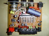
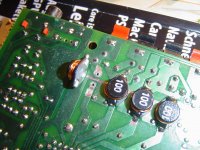
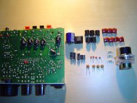
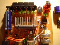
just want to share my "version" of modding this little beast. First i changed the potentiometer, the old on was garbage...
The new op amp is the OPA 2134 PA, don't know if this mod helped much. I also changed the input caps, resistors, coils of the signal path...
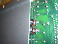
I moved some components to the backside, like the coils which are smd ones with 3.8 A. It is really tight between the coils and the case - but it fits.
Regards QT
Hi,
just want to share my "version" of modding this little beast. First i changed the potentiometer, the old on was garbage...
The new op amp is the OPA 2134 PA, don't know if this mod helped much. I also changed the input caps, resistors, coils of the signal path...
I moved some components to the backside, like the coils which are smd ones with 3.8 A. It is really tight between the coils and the case - but it fits.
Regards QT
Attachments
Have these amps got the 'Overshoot Protection' Shottky diodes fitted in their original as built condition?
These are important if you're driving the thing hard or into 'difficult or unusually reactive' loads....
--If not, this could be the reason for some unexplained TA2020-020 chip failures....
These are important if you're driving the thing hard or into 'difficult or unusually reactive' loads....
--If not, this could be the reason for some unexplained TA2020-020 chip failures....
After a 3 week wait my Lepai finally showed up at the post office. Thing worked great right out of the box but...
I was fooling around seeing how low I could set my mp3 player and still get an 'as loud as a normal human being can stand' level out the speakers. Dreaded silence and the 'light ticking' sound hit me after about 3 minutes of this.
Oh well, already found an eBay supplier that sells chips two for $12 including postage.
Alastair,
From the data sheet
"Diodes D1, D2, D3 and D4 are only required for applications where VDD>13.5V"
The other 4 are there. I checked the 'cheap' smps that came with the amp and it was 13.9V before the on board 'make sure you didn't plug it in backwards' diode. Couldn't check it under a load but it seems close. My speakers are 4R nominal and 3.9R measured with a DVM.
When I get parts and repair it I will try using a lower supply voltage. Things do seem to be just a little odd: No clipping or distortion then just silence with 1Hz ticking.
Rick
Overshoot protection..
Aye, Thats the 'mode-of-failure' as I recall years ago when I was developing with these chips.
There was somewhere on the Tripath website a single leaf concerning the overshoot issue. --Bearing in mind this was some years ago, I recall that the diodes should be included where 'unusual loads' were expected or when you use the outputs parralelled together (with the appropriate DC Offset correction/servo etc.) to drive 2 ohm loads.
I successfully drove a 2 ohm load with a single channel, ie- four 4 ohm speakers in two pairs driven by one chip and at 14-14.5V for many hours with no apparent damages--Sounded pretty good too, An old pentium heatsink with no fan was added as a precaution as driving a 2 ohm load did make it heat somewhat! ...
As the diodes have no other function and dont affect the sound, it maybe an idea to add 'em anyway--I did in all the schems I used these chips in....
Hi, remove the zener which is connected to the fault pin, the amp will not kill TA2020 IC's then, read the TA2020 datasheet to see why.When I get parts and repair it I will try using a lower supply voltage. Things do seem to be just a little odd: No clipping or distortion then just silence with 1Hz ticking.
Rick
Hi, remove the zener which is connected to the fault pin, the amp will not kill TA2020 IC's then, read the TA2020 datasheet to see why.
Looking at mine it is silk screened as a 4148 which is a small signal switching diode. Did they actually use a zener there?
I haven't looked closely but it appears they included it as part of their left handed, cross eyed scheme for a power switch. Normally it is OK to use blocking diodes for combinational logic i.e. [if the on off switch or the fault pin go high then mute system] but there is only one diode here so it has me a bit wary.
Data sheet shows mute pulled up internally on the chip so it should be should be pull down to turn on, float or high to turn off. Mind fart but it looks like the diode is backwards in that case. i.e. if fault is high, mute is already high from pull up. If fault is low, diode blocks it from pulling mute low. IOW it doesn't do anything.
http://img23.imageshack.us/img23/1586/scan10006k.jpg
The only zener I can see is in the overvoltage circuit which combines with the fault pin to mute.
Rick
I changed the circuit just a bit. Moved diode in power supply circuit, reversed diode in protection/fault circuit, and added diode in over voltage protection circuit so fault and over voltage function as NOR<?>.

This should keep the inductor from burning out if the amp gets reversed voltage and let the fault and over voltage protection work. I'm open for comments or corrections but IMHO I would like to keep this particular focus on circuit corrections and safety rather then improvements like changing out the op amp.
For example: I added the protection diodes as per Alistair's suggestion.
Just as a for instance, the over voltage protection seems unnecessarily complicated. I'm trying to think back to single transistor designs I made with a PNP transistor vs. two NPNs to KISS.
I haven't put the changes in yet as my replacement TPA2020 isn't here yet. I have the schematic up on my personal web space which earthlink sees fit to limit to 10 megs so I don't know how long I will keep it up.
Rick
I'lll have to check my unit, but I have a feeling they did. I seem to remember it was between the mute pin and the fault pin, but I need to open my unit to be sure.Looking at mine it is silk screened as a 4148 which is a small signal switching diode. Did they actually use a zener there?
I wanted to wire up a fault LED on my unit, so I removed whatever was connected to the fault pin (i'm 99% sure it was a zener) and instead wired an LED in series with a 2k resistor. It works and I quite like having a fault LED.
To make matters worse, there are 2 different versions of this amp, and we could have differing versions...
Nice work with the schematics btw.
I have updated the tone control on my amp, but now it is acting up. When I plug it in it works fine for a few seconds then the LED starts to flicker and the sound "hacks" but the music is still audible and sounds fine.
Hi res photos of my board.
http://upload.landslide.nu/upl/Tornado/_DSC3941.jpg
http://upload.landslide.nu/upl/Tornado/_DSC3942.jpg
Hi res photos of my board.
http://upload.landslide.nu/upl/Tornado/_DSC3941.jpg
http://upload.landslide.nu/upl/Tornado/_DSC3942.jpg
Changing the Pots
New to the forum but have recently gone down the modified Lepai T-Amp route coupled with pair of home-made Cyburg Needle TQWT speakers (still under construction) to complement my new 46" Panasonic Plasma TV.
Progress so far:
a) have changed 3.3uF input Caps to 2.2uF MKT types
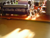
b) swapped 2200uF for 4700uF Panasonic FC
c) changed all other 3.3uF electrolytics for 2.2uF Panasonic FCs
d) changed 330uF for 470uF Panasonic FC
e) swapped op-amp for NE5532P
7f) added d.c. trimmers etc. (as per #465 on Pg 47)
Still to do...
g) change tone circuit capacitors and resistors (#484, Pg49)
h) change out Pots for better ones
and possibly...
i) add remaining 4 shottky diodes
j) replace 10uH inductors
my question is: do the control knobs come off in one piece or are they fixed to the pot spindles?
Given previous reference to risk of breakage, I have tentatively attempted to prise them off but unsuccessfully. Ideally I would like to re-use the existing control knobs.
Cheers
New to the forum but have recently gone down the modified Lepai T-Amp route coupled with pair of home-made Cyburg Needle TQWT speakers (still under construction) to complement my new 46" Panasonic Plasma TV.
Progress so far:
a) have changed 3.3uF input Caps to 2.2uF MKT types
b) swapped 2200uF for 4700uF Panasonic FC
c) changed all other 3.3uF electrolytics for 2.2uF Panasonic FCs
d) changed 330uF for 470uF Panasonic FC
e) swapped op-amp for NE5532P
7f) added d.c. trimmers etc. (as per #465 on Pg 47)
Still to do...
g) change tone circuit capacitors and resistors (#484, Pg49)
h) change out Pots for better ones
and possibly...
i) add remaining 4 shottky diodes
j) replace 10uH inductors
my question is: do the control knobs come off in one piece or are they fixed to the pot spindles?
Given previous reference to risk of breakage, I have tentatively attempted to prise them off but unsuccessfully. Ideally I would like to re-use the existing control knobs.
Cheers
Last edited:
Hello everyone
I installed the relay amplifier
Get lost in the noise when turning
Turn off the power when the noise occurs Unfortunately
(Sorry for the automatic translation)
I installed the relay amplifier
Get lost in the noise when turning
Turn off the power when the noise occurs Unfortunately
(Sorry for the automatic translation)
An externally hosted image should be here but it was not working when we last tested it.
- Status
- This old topic is closed. If you want to reopen this topic, contact a moderator using the "Report Post" button.
- Home
- Amplifiers
- Class D
- Lepai T-Amp with TA2020