I am testing my own layout for the iraudamp1, having followed their schematic exactly. I am using all the same components also. I wanted to do this first to get something working so I can understand the thing and then go on to modifying the design. I could not get self-oscillation at 300khz with the original component values. It maxed out at about 200. I assume this means my layout is causing more phase shift than theirs. I lowered the integrator caps to 510pf instead of 1000. Now it is oscillating at 340kHz and the switching waveform looks fine; good square wave with no significant ringing. But if I feed a sine wave audio signal, the output starts to become a triangle wave at about 7V, irrespective of the load. At first I thought it must be choke saturation, but I now have a large RM core choke in there and it is definitely not saturating and the waveform starts to distort at the same level. For testing I am using +/- 35V regulated bench supply. I noticed there were several people with experience of this amp on the forum. Any ideas what I should check?
are u sure that your choke is properly wound and that has needed inductance ~18uH, where did you put 470u caps, and post some hires. picture of device . . .
BTW you can use 5k pot. for frq. adj. to make room for wider phase comp. which will in the end make possible oscill. at higer freq.
BTW you can use 5k pot. for frq. adj. to make room for wider phase comp. which will in the end make possible oscill. at higer freq.
re. iraudamp1 problem
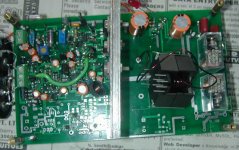
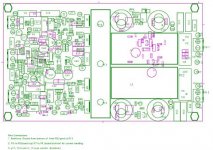
Thanks for the input. Attached is a picture of the amp as it is now...only one channel parts are in and the heatsink is just a temporary one as is the mounting of the choke. The layout is for a gapped toroid but I don't have one yet. I've also attached my copy of the schematic...as I said as far as I know it follows the IR. Also including the top silk screen layer to show where the parts are placed. One thing I should say, we are doing this over in India as a education project (I'm teaching some guys) and critical parts are not easily available (like the high speed mosfets...), so I take a lot of measures not to blow anything during the development stage. We are running off a bench supply with selectable current limiting. The large (10,000 mfd) electrolytics outside the board were necessary because of the long line from the supply to the board under test.
I naturally suspected the choke first, but can't find anything wrong. We have a meter and it is 15microhenry (IR said 10 but I realized that was too low). We made one like this for an SMPS with 50V out loaded at 3A and it worked fine. As you see there is ample room to add a few turns which I will do. But the problem of the audio sine wave becomming a triangle wave seems to be independent of the choke. I had a 10 microhenry commercial choke for the first test and the only difference was that there was too much carrier coming through the filter. Moreover that choke probabably was near saturation. But the waveform distortion started at the same voltage (about 7V). And it is the same irrespective of the load...open, 8 ohms or 4 ohms, so it is not current related.
Tomorrow I will try your suggestion about the integrator, and see if that somehow helps.
Attachments
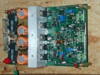
First of all, where u putted the 470uF cap. from what i see in that picture, it seems to be a little bit far from the transistors. u should put them as close as possible to the transistors, and also try to put some non pol. capacitors, 100-470nF, solder them dirrectely on to transistors legs. I had a simillar problem with a class T amp, and i solve the problem by just putting the caps. very close to the IC.
thanks. It appears that the problem was in fact the lower capacitors on the integrator. Taking zkaiser's suggestion I replaced the 1K trimmer with 5K and put back the 1000pf caps and now the output looks OK. I will increase the choke turns a little now as there is now more carrier coming through, and will also put bypass caps directly on the pins of the MOSFETs as suggested by Crriss. Since the position of the 470 UF caps didn't seem to be the basic cause of my problem, I'll only change that in my next layout. Thanks for the help.
The LT1220 and THS4051 are video op amps. Their slew rates and GBP are much higher than the LM318 (250v/µS 45Mhz vs 50v/µS 15Mhz). That said, I can't say whether or we really need that much slew rate to drive the integrator at 300kHz. But I'd want to have a working amp with the LT1220 and then try to drop in other op amps and compare the result, rather than trying the 318 first.
Yea, I've made a few of these now. The electrical measurements are fine. As with all class D, there is a residual of the carrier at the output which makes THD measurements a little difficult with normal equipment. But looking at the residual in the scope, I think the distortion is very low at low power levels. I've also been able to use 200V mosfets, raise the input voltage to +/- 68V and get 200W into 8ohms. It requires a few modifications to the power supply section of the circuit (and also the feedback filter).
I have been powering these with my own design of SMPS. We are having more trouble with that than the Class D.
As for ears, so far we've only used them a bit for PA where subtlety was not going to be audible. I do intend to eventually use them in an environment where I can directly compare them with a high quality class AB amp. but we are not there yet.
It should be noted that IR has an iC now, IRS2092, that basically incorporates the whole front end of the IR1 amp topology (op amp integrator, comparator + level shift, gate drive and also over current and over voltage protection). Also the dead time is trimmable on that meaning if you want to tweak it you should be able to minimize distortion by minimizing dead time for the actual mosfets in use. I have not had a chance to try these but hope to do so in the next couple of months.

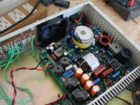
sorry it took a while. The finished amps are not in my workshop and I couldn't get a hold of one for a picture. Here is one under construction...the SMPS is shown in the chassis but the amp is removed because we had some problems with it. This box is going to hold two IR class D boards for 4 channels of audio at about 200W per channel. The Class D board is a direct copy of the IR amp 1. I am using THS4051 video amp for the integrator op amp, and STP20NF20 mosfets in this version. The board works fine at a supply of +/-50V but that will only give about 100W into 8ohm load and our loads are all 8ohms. At 65V supply it will give 200W, some component changes are needed and some things (like the 12V switcher for VDD and relay should be redesigned. I am getting some IRS2092 ICs and my next design will use those. I'll redesign the power supply section and get VDD and relay power from a separate winding on the SMPS output.
The SMPS is comletely my own design, but it is problematic. It is a half-bridge current mode design. But there is jitter in the PWM and other problems. I am going to next experiment with a cascaded design with a buck stage feeding a bridge or push-pull.
The SMPS is comletely my own design, but it is problematic. It is a half-bridge current mode design. But there is jitter in the PWM and other problems. I am going to next experiment with a cascaded design with a buck stage feeding a bridge or push-pull.
Attachments
I have two iraudamp1 boards that seem to be almost direct copies of the eval layout. One board didn't have any FETs when I got it, so I put FDP42AN15A0 on both boards. They work and sound excellent.
I have one really lame question though. Does the switching freuqency go higher or lower with a higher value R26/R27? What would the frequency be at say 1k vs. 500R?
EDIT: OK, make that two lame questions. Should both channels have their frequencies matched exactly, or should they differ slightly?
I have one really lame question though. Does the switching freuqency go higher or lower with a higher value R26/R27? What would the frequency be at say 1k vs. 500R?
EDIT: OK, make that two lame questions. Should both channels have their frequencies matched exactly, or should they differ slightly?
- Status
- This old topic is closed. If you want to reopen this topic, contact a moderator using the "Report Post" button.
- Home
- Amplifiers
- Class D
- iraudamp1 problem