my brother went on vacation and took the camera with him so no pictures for now.
update:
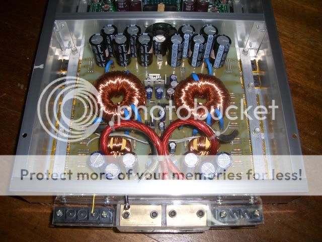
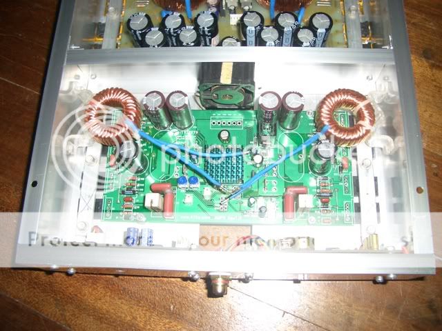
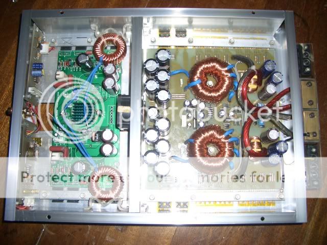
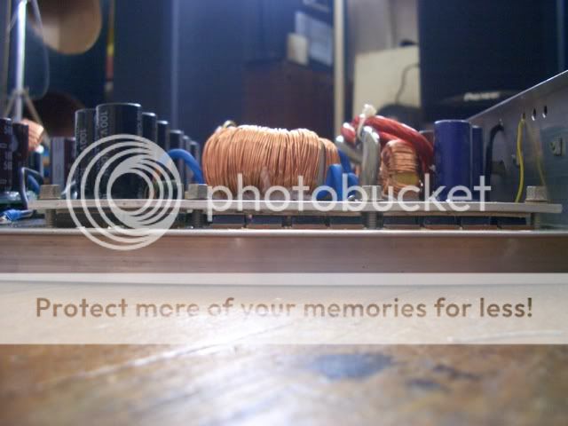
I have completed the powersupply
the transformer I used has 6T+6T pri and 28T+28T sec. one of them has an aux 4T for 5V supply and the other has aux 9T for +/-15V supply.
output voltage is +/-68V idle with 15V input just before input overvoltage prot kicks in. (Tripath chipset max input is 70V)
freq is 40kHz idle current is 200mA (entire supply draw including gate drive and TL494 circuit) with output rectifiers and snubbers not yet installed.
edit: I installed the snubbers and realized the ones at the secondary is too small. increased the resistance then all is well.
also, the gate drive is 16V peak and maintains regulation down to 10V.
update:
I have completed the powersupply
the transformer I used has 6T+6T pri and 28T+28T sec. one of them has an aux 4T for 5V supply and the other has aux 9T for +/-15V supply.
output voltage is +/-68V idle with 15V input just before input overvoltage prot kicks in. (Tripath chipset max input is 70V)
freq is 40kHz idle current is 200mA (entire supply draw including gate drive and TL494 circuit) with output rectifiers and snubbers not yet installed.
edit: I installed the snubbers and realized the ones at the secondary is too small. increased the resistance then all is well.
also, the gate drive is 16V peak and maintains regulation down to 10V.

hopefully the board doesn't break. 
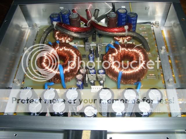
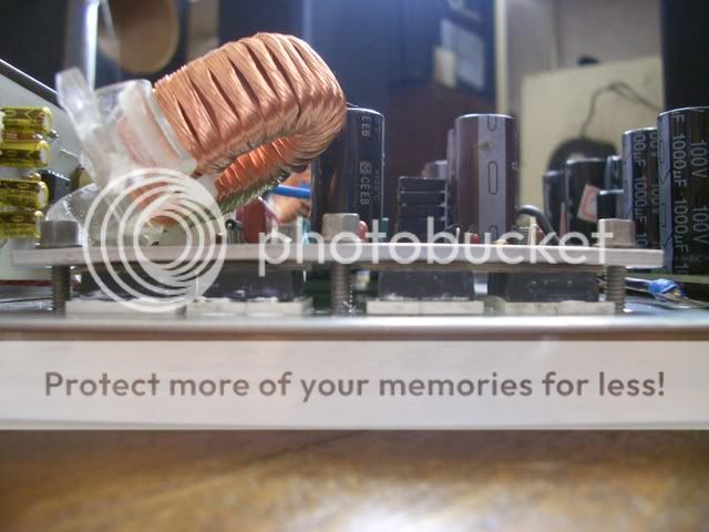
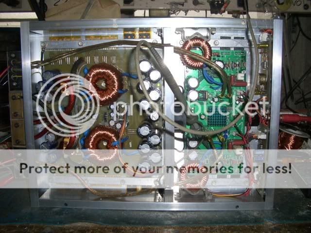
I will use silicone around the trafo's so that vibration won't knock them off.
knowing that the trafo's will be heavy, I added mounting holes on the PCB right under the trafo's.
a few more measurements:
over voltage cutoff is lowered to 14.5V. above that, the supply shuts off.
at 14.5V input just before the supply shuts down, output voltage is +/-68V (+/-70V = maximum voltage of the tripath chipset)
with everything installed, current draw is 390mA idle
waveforms are near perfect square waves with sloping sides. absolutely no spikes or ringing of any sort.
I hope it holds up. I'm having second thoughts if I would remove a turn off the trafo to drop the voltage a bit.
the voltage goes up to +/-68V when there is no load and input is about 14.5V just before the overvoltage trips and shuts the supply down.
how much wire? the amp now weighs a lot.
each primary is about 14" long, the secondary is about 9feet. those are estimates BTW. never thought about measuring them before winding. hehe
Hi
I think if you will do full test, do it with lights on, if worried still, take one turn off, but I think if you have another amp, voltage won't be that high to kill chip... Up to +/-70V you can go: Absolute Maximum Ratings indicate limits beyond which damage to the device may occur.
I think if you will do full test, do it with lights on, if worried still, take one turn off, but I think if you have another amp, voltage won't be that high to kill chip... Up to +/-70V you can go: Absolute Maximum Ratings indicate limits beyond which damage to the device may occur.
I have two other amps one for the front speakers and another for the rears. so that might take care of the voltage.
only soldering the fets to the amp8 board and wiring them together is all that's left and then testing if it will run.
I was thinking of first testing it to its limits (input voltage only. I don't have a high current 12V supply) at the bench first.
run it up to max till the SMPS shuts down and see how it deals with restarting after a fault then install in car for power testing. hopefully I don't let the magic smoke out.
Hey, I don't mean to take this offtopic, but i also want to build an amp8 but for home use.
a 1000va toroid will be extremely heavy, so how hard would it be to make a SPMS like you have done, but that runs from 240v instead of 12v?
Would it simply be a case of having 20 times less windings on one of the toroids?
a 1000va toroid will be extremely heavy, so how hard would it be to make a SPMS like you have done, but that runs from 240v instead of 12v?
Would it simply be a case of having 20 times less windings on one of the toroids?
Gotcha, I guess there's not really as much risk when running things from 12v as there is from 240v.djQUAN said:nope. you will have to redesign the whole circuit.
I have built several SMPS's for car use but haven't had the guts to make an offline SMPS yet.
the risk of burning your house down or killing someone is possible when you don't have enough experience with those things.
I don't really know much at all about doing your own SMPS, so I may just go with a toroid for now, and build or buy an SMPS later on.
Also, have you thought about putting a few high current schottkey diodes on yer PSU rails? each one should knock 0.5v or 0.7v off the rails which would result in less chance of ever giveing the AMP8 70+v.
Just have say 5 in series for 2.5v drop. EDIT: Just one more quick question, would it be very difficult to build a 25v psu that runs from 12v car battery? I would need around 10a of output current, so run an amp9 at full power in my car... If you know of any good links or info on where to start that would be great. I don't mind winding own toroids as I have loads and loads of solid copper wire.
it's playing music!!!!!
here's how my workshop floor looks like right now.

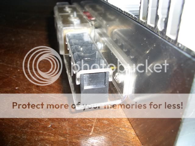
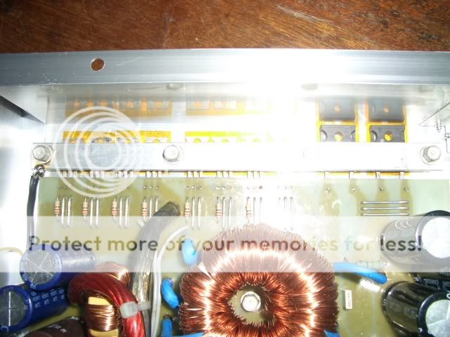
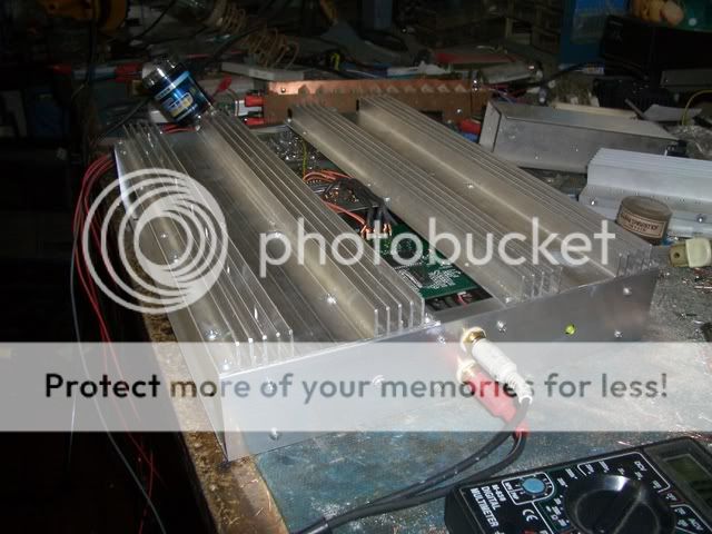
how the fets are mounted
it's alive!!!!
some waveforms:
gate drive 5v/div

primary waveforms:
took that with the ground lead connected to chassis. don't know if that was causing the spikes. the heatsink stays cool. 10v/div

after the half bridge:
20v/div

the thing on the bench:
and then it blew!!! It was playing then I heard a very loud pop then the safety bulb in series with the supply glowed.

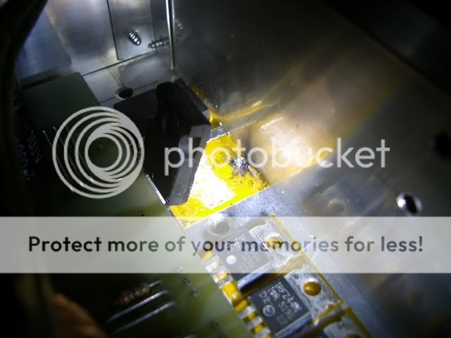
a metal flake must have gotten under the kapton tape.
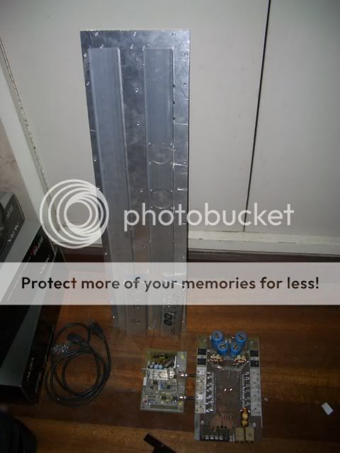
the old chassis and boards:
here's how my workshop floor looks like right now.
how the fets are mounted
it's alive!!!!
some waveforms:
gate drive 5v/div
primary waveforms:
took that with the ground lead connected to chassis. don't know if that was causing the spikes. the heatsink stays cool. 10v/div
after the half bridge:
20v/div
the thing on the bench:
and then it blew!!!
It was playing then I heard a very loud pop then the safety bulb in series with the supply glowed.
a metal flake must have gotten under the kapton tape.
the old chassis and boards:
- Home
- Amplifiers
- Class D
- Big-t