time for a rebuild....
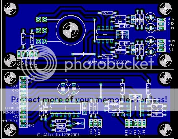
plans for a new chassis layout, new SMPS and preamp boards.
following eva's advice and to try out something new, I decided to incorporate 18V gate drive to the SMPS fets.
a few things about the supply....
-board width same as amp8 pcb lenght
-has thermal and input overvoltage protection
-18V gate drive for the switching fets for lower switching losses
-lots of input and output capacitance (if I can get caps to fit in the layout)
-direct to board power input connections (basically, power wires go straight to the board. no on-board connectors)
-already includes the +5V and +/-15V supplies for the chipset and preamp circuitry
-single layer board!!!! I didn't want to spend extra cash for new blank boards and going single layer made etching easier. took about 49 jumpers in all. many are paralleled as they carry high current. high current tracks in confined areas have 15ga copper wire soldered to the tracks for more current capacity.
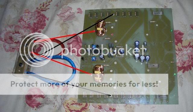
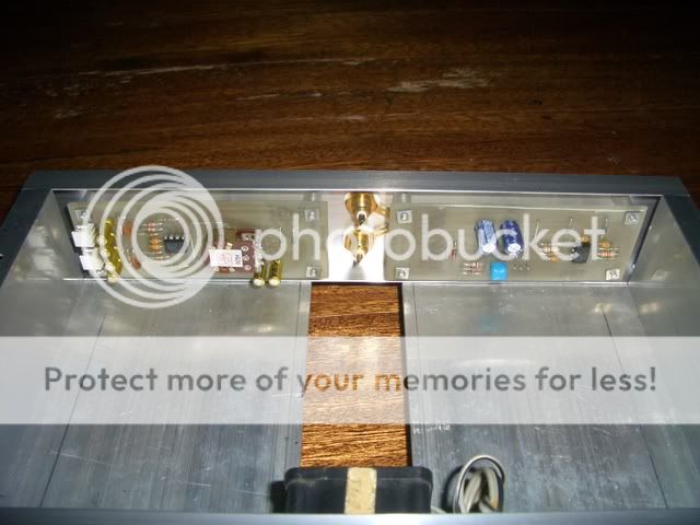
here are a couple of pics of the power input terminal blocks from 3/4" square brass bars that I made using a drill press, taps and a grinder.
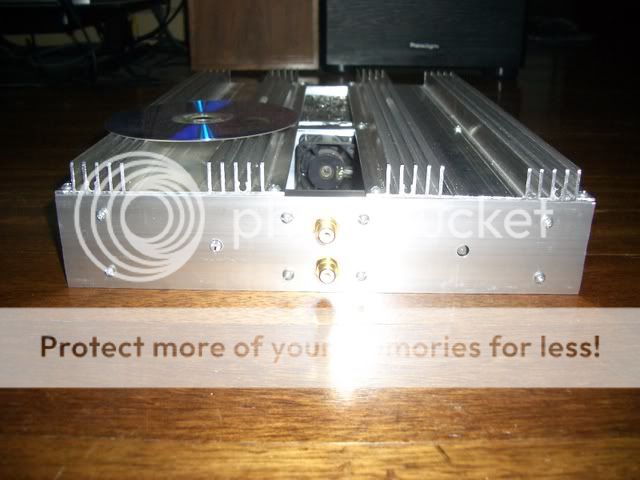
front and top view:
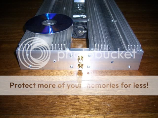
bottom and rear view:
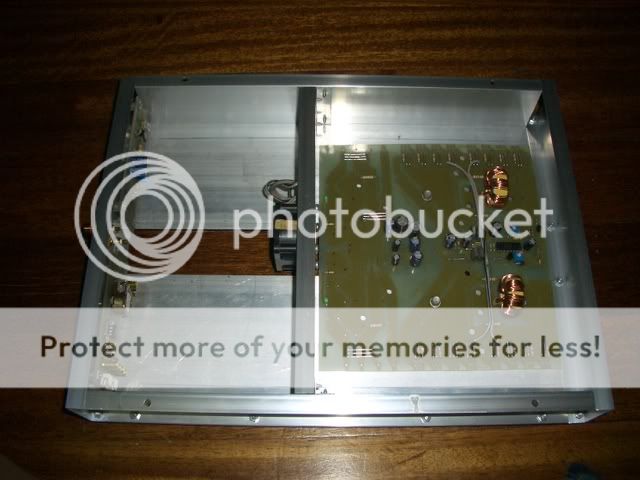
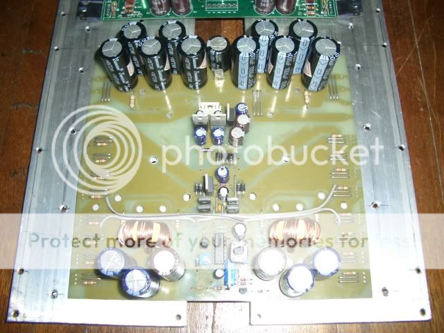
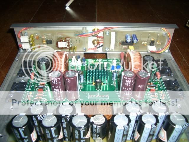
and here's a photo of the partially populated board and how the terminal will be put to use.
plans for a new chassis layout, new SMPS and preamp boards.
following eva's advice and to try out something new, I decided to incorporate 18V gate drive to the SMPS fets.
a few things about the supply....
-board width same as amp8 pcb lenght
-has thermal and input overvoltage protection
-18V gate drive for the switching fets for lower switching losses
-lots of input and output capacitance (if I can get caps to fit in the layout)
-direct to board power input connections (basically, power wires go straight to the board. no on-board connectors)
-already includes the +5V and +/-15V supplies for the chipset and preamp circuitry
-single layer board!!!! I didn't want to spend extra cash for new blank boards and going single layer made etching easier. took about 49 jumpers in all. many are paralleled as they carry high current. high current tracks in confined areas have 15ga copper wire soldered to the tracks for more current capacity.
here are a couple of pics of the power input terminal blocks from 3/4" square brass bars that I made using a drill press, taps and a grinder.
front and top view:
An externally hosted image should be here but it was not working when we last tested it.
bottom and rear view:
An externally hosted image should be here but it was not working when we last tested it.
and here's a photo of the partially populated board and how the terminal will be put to use.
Isn't this power supply a bit overkill? I think that you could do with half that, or at least in half that size. Single sided boards are easier and cheaper to make, but this comes at the expense of extra EMI and space used. That's why I designed such a tiny push-pull SMPS for my car amp, and it worked fine for 2x150W class D despite the size. You are doing a great job anyway
Eva,
well, this would be used for sub duty and I'm expecting to drive this into clipping and will be playing bass heavy music (yeah I know, you guys hate boom setups. but this system will be designed for good SQ but have bone crushing bass when called upon. ) besides, since I'm already building my own amp, why not over-engineer?
I haven't had issues regarding EMI with the first SMPS and that was with a metal case and an acrylic top. this one will be in an all alu case. hope that helps reduce EMI.
I don't have the right component (zener) in my parts bin to provide 18V gate drive but with the components right now, I have regulated 15V gate drive right at the fet gates. do you think that is enough or will 18V have better performance compared to 15V?
some updates:
well, this would be used for sub duty and I'm expecting to drive this into clipping and will be playing bass heavy music (yeah I know, you guys hate boom setups. but this system will be designed for good SQ but have bone crushing bass when called upon.
) besides, since I'm already building my own amp, why not over-engineer? I haven't had issues regarding EMI with the first SMPS and that was with a metal case and an acrylic top. this one will be in an all alu case. hope that helps reduce EMI.
I don't have the right component (zener) in my parts bin to provide 18V gate drive but with the components right now, I have regulated 15V gate drive right at the fet gates. do you think that is enough or will 18V have better performance compared to 15V?
some updates:
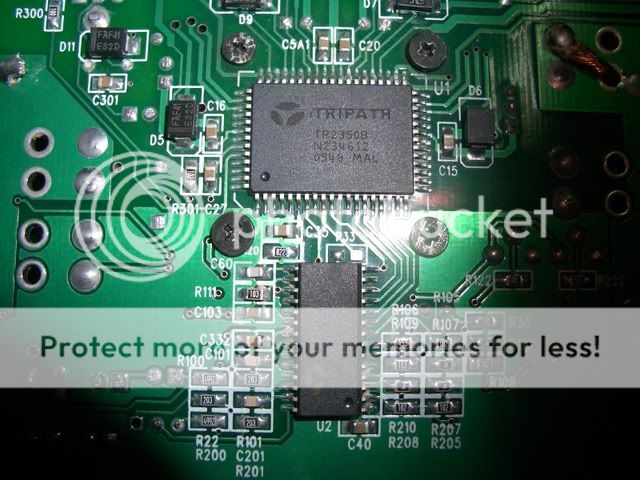
yes, they are STW34NB20.
the tripath datasheet says that two pairs per side of those fets are the maximum that the chipset could drive.
the driver chip gets so hot that although the chip itself is soldered to the PCB and a heatsink is not enough. it still needs a bit of fan cooling.
the tripath datasheet says that two pairs per side of those fets are the maximum that the chipset could drive.
the driver chip gets so hot that although the chip itself is soldered to the PCB and a heatsink is not enough. it still needs a bit of fan cooling.
here's the fet:

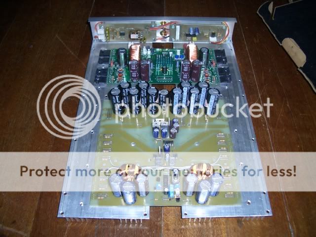
was busy with other things so not much was done. I just rewound the toroids and made little mounts for them.
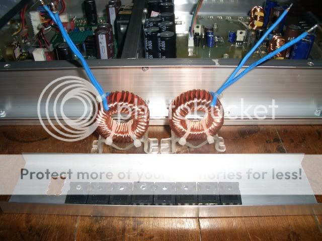
I don't want to mount the coils off-board but they won't fit the casing when board mounted and the vibration will break the wires off so I have to mount them to the chassis.
was busy with other things so not much was done. I just rewound the toroids and made little mounts for them.
I don't want to mount the coils off-board but they won't fit the casing when board mounted and the vibration will break the wires off so I have to mount them to the chassis.
Hi
It would be nice if better fets would be used, since this ones are old, and not that good, not compared to what you can get this days... Whole thing look every time better and better, I like how you made inductors... One thing you can be sure is that if you would use epoxy or hot glue, indictors would be fine standing on boarf itself...plus I don't think that there is that big vibrations that wire would be broken or damaged in any way
It would be nice if better fets would be used, since this ones are old, and not that good, not compared to what you can get this days... Whole thing look every time better and better, I like how you made inductors... One thing you can be sure is that if you would use epoxy or hot glue, indictors would be fine standing on boarf itself...plus I don't think that there is that big vibrations that wire would be broken or damaged in any way
15V is great provided that you still get them when input voltage drops to 10V. In some amplifiers effective Vgs (right at the g-s terminals) drops to 7V with 10V input and this is the situation we are trying to avoid.
I still think that you could make it smaller, including smaller transformers. Check IRF2907Z MOSFETs too. Maybe for your next version...
I still think that you could make it smaller, including smaller transformers. Check IRF2907Z MOSFETs too. Maybe for your next version...
problem is, any component that is just new or just released cannot be found here. so I use old, readily available components.
luka,
the fets I'm using are the ones provided in the 41Hz kit when I got it. and even those fets I have to order online. so for newer ones, I also have to order online. not easy when you don't have a credit card.
the problem I'm having with the inductors is the height. when standing up, it is taller than the side walls of the case. mounting them at an angle is not an option as there are supply caps on one side and output terminals on the other side on the board so there is little room to play with.
eva,
I estimate the 15V gate supply remains constant right down to 9-10V Vin. when I complete the supply, I will test how low an input voltage it can hold the gate supply to 15V
the actual regulated supply is 17V (input voltage multiplied by 2 then passed through a 317 regulator) and after the losses in the circuits, we get 15V (top of the square waves) right at the gates.
well, I'm not as experienced as you (and with even less available resources) so this may do for now. but we'll see in the future if I can make an even smaller high power SMPS
dj, what output power is the amp? I can send you a couple of T106 MPP cores to experiment with if you'd like. I could also send some 18 awg wire to wind the cores with. They look like the picture in this post: http://www.diyaudio.com/forums/showthread.php?postid=1048331#post1048331
These are some easy online sources for toroids in various materials (standard iron powder, RF iron powder, MPP, Hi-Flux, Kool-Mu, Ferrites). Some accept Paypal :
http://kitsandparts.com/toroids.php
http://www.cwsbytemark.com
http://www.amidoncorp.com/
I've had a successful order with the first one and a second order is on the way. I have not yet tried the other two.
Check this thread too:
http://www.diyaudio.com/forums/showthread.php?s=&threadid=113413
Check this deal on MPP cores on ebay too, they suit class D quite well (Search for "arnold toroid"):
http://search.ebay.com/search/search.dll?from=R40&_trksid=m37&satitle=arnold+toroid&category0=
To decide the right size and material of an iron powder toroid for a power inductor, you have to consider three factors:
1 - Core losses: These are dependent only on the AC voltage applied to the core and to the frequency. They are not dependent on current so the core will get equally hot no matter if no power or 1KW is being delivered to the load. For a square wave use the following formula:
B=V*T*10^8/(N*AE)
B=Magnetic flux in gauss
V=Peak voltage applied to the winding in each direction (ie: 50V for +/-50V class D)
T=Time elapsed since inductor ripple current crosses 0 until it reaches peak value (ie: 2.5us for 100Khz operation, usually 1/4 of period)
N=Turns
AE=Core cross-sectional area in cm^2
Then you take B value and look up power loss versus B and frequency (in mW/cm^3 in) core material data tables. Values around 100mW/cm^3 are ok. Multiply this value by core volume and you get total power dissipated on the core.
2 - Saturation: The core will progressively lose magnetic properties and turn into an air core as current exceeds a certain value. Then it will recover as current is reduced again. This process is very progressive for iron powder. To know how much inductance remains for a certain current level, core and turns use the followind formula :
H=.4*3.1415*N*I/LE
H=Magnetic field strength in Oersted (1 Oe = 80 ampere-aurns per meter)
N=Turns
I=Current (instantaneous value)
LE=Effective core magnetic path length in cm
Then go to the core material datasheet and look up percent permability (or remaining permeability) for the H value obtained and calculate actual inductance based on it (actual L = nominal L * % permability), (or actual L = nominal L * actual perm. / nominal perm.) A 2:1 inductance reduction at maximum allowed current is reasonable. For example, 60u MPP cores will produce approx. half the inductance when H has reached 100.
3 - Winding losses: This one is really easy...
R=.017*L/S
R=winding resistance
L=winding length in cm
S=wire cross-sectional area in mm^2
P= Irms^2*R
You are up to the job of estimating typical and worst case rms current through the winding. A few watts of losses are fine, from 4-8W or so for T106 cores to 10-15W or so for T200 cores (assuming thick windings).
You can find data on various core materials on www.micrometals.com (online tables) and www.arnold.com (tables in MPP catalog)
Final tip:
When you need to increase saturation current and reduce core losses, and space is limited thus preventing your from using a higher diameter core, stacking two cores with shared winding(s) may solve the problem. This situation is analysed as if there were two separate inductors in series, each with the same amount of turns as the combined one.
Lets assume we have a single core with 20 turns that needs to be improved in terms of core losses and saturation current. We would achieve the same inductance with two stacked cores and 14 turns. Magnetic flux (B) in each core would be 70% of the previous value so losses in each core would be halved resulting in cooler operation, although total core losses are still the same. Magnetic field strength on each core would be also 70% of previous value too, so saturation current is increased.
- Home
- Amplifiers
- Class D
- Big-t