Hi Guys,
I finally took the plunge and ordered SPS80 from coldamp for my UCD400. This is the unmodified +/-60V version. Before I connect it up to my UCD, I have done some test and would like to share with you
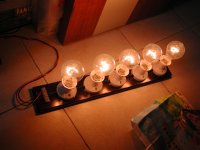
The test was performed by connecting the output of SPS80 to a number of light bulbs connected in series.
When there is no loading, the output is 120V.
When the loading current is 0.2A, the output voltage is 118.3V
When the loading current is 3.7A, the output voltage is about 118.0V. As the temperature rises, the voltage increased back to 121V in about 30 minutes. At that time, the aluminum plate became quite hot at about 62C, the Inrush limiter has a temp of about 70C. The input capacitors were warm at about 40C. The output caps were only slightly warm. The transformer was about 50C. But all these was WITHOUT extra heatsink, just with the original aluminium plate.
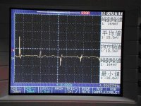
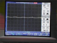
The picture below indicated a 170KHz pulse, most probably coming from the carrier frequency of 85KHz. But not sure why it is doubled?? Amplitude is about 2V. Putting the supplied choke on do not make much difference in the current setup.
When the load increased to 3.7A, the transformer starts to buzz at a very very low noise. Can only hear with the ear really close.
After testing for 30 minutes, I switched off the modules, but cannot switch it on againuntil 30 min later. May be because the heat has triggered the startup protection circuit with this continuous loading¡K¡K
Will report on the use on UCD later
I finally took the plunge and ordered SPS80 from coldamp for my UCD400. This is the unmodified +/-60V version. Before I connect it up to my UCD, I have done some test and would like to share with you
The test was performed by connecting the output of SPS80 to a number of light bulbs connected in series.
When there is no loading, the output is 120V.
When the loading current is 0.2A, the output voltage is 118.3V
When the loading current is 3.7A, the output voltage is about 118.0V. As the temperature rises, the voltage increased back to 121V in about 30 minutes. At that time, the aluminum plate became quite hot at about 62C, the Inrush limiter has a temp of about 70C. The input capacitors were warm at about 40C. The output caps were only slightly warm. The transformer was about 50C. But all these was WITHOUT extra heatsink, just with the original aluminium plate.
The picture below indicated a 170KHz pulse, most probably coming from the carrier frequency of 85KHz. But not sure why it is doubled?? Amplitude is about 2V. Putting the supplied choke on do not make much difference in the current setup.
When the load increased to 3.7A, the transformer starts to buzz at a very very low noise. Can only hear with the ear really close.
After testing for 30 minutes, I switched off the modules, but cannot switch it on againuntil 30 min later. May be because the heat has triggered the startup protection circuit with this continuous loading¡K¡K
Will report on the use on UCD later
Attachments
Thanks Ackcheng, for your time.
Some comments to your tests,
-The efficiency of the supply is around 96%, that means that at the output level tested (444W), dissipation is around 18W, enough to make the plate hot if no additional heatsinking is provided, specially when that power is delivered CONTINUOUSLY during 30min.
That condition is FAR above the typical music requiremens even with 1KW amplifiers, and even then, the temperature rise was "only" 37ºC above ambient. Just screwing the supply to the case is enough to keep it much cooooooler.
Anyway, this tests demonstrate that the supply can operate with no additional heatsink at very high power levels.
-The small switching residue is doubled in frequency due to the fact that the output is full-wave rectified, thus the 85KHz switching frequency is doubled.
Note that using the supplied small chokes in series will prevent any noise entering the amplifier, (forming an additional LC lowpass with the onboard bypass caps). This quietness has been demonstrated by other users with our own BP4078 modules and also Hypex's and LCAudio's. (there are some reviews in this forum)
-It is normal to hear some small "buzz" under heavy loading, due to magnetostriction. I doubt you will notice it when you are outputting 440W of music power!
-About the thermal protection: the startup circuit is designed to operate on cranking only, for a short period. If, for any fault condition such as a sustained shortcircuit at the output (overcurrent protection triggers) the supply cannot start, this startup circuit would overheat, that's why a thermostat was added to protect it.
As you have tested the supply with no heatsink and the chassis reached 62ºC, it may have heated up the thermostat, reaching the required 55ºC to cut-off starting circuit. That's why once you stopped the supply you couldn't start it again until it cooled down.
This is not an issue as this condition won't happen with proper mounting on the chassis and music use, of course, as the supply won't ever reach 62ºC (that is a completely safe temperature, on the other hand).
That's good test! Test it now with a 1000W PAR64 bulb...This kind of bulb have nears 0.2 ohms cold and go nears 13 ohms hot! That's a really good test to try the pulsed current capacity of a power supply! I do that test on all my 6.5Kw power supply for my HVI serie with 2 of these in parrallel at 190V! Most of the time, my 20A Breaker trip when power lose function is dissabled on power supply. A cure to this is bigger storrage cap at the input of switching.
A cure to fix the probleme of residual noise on DC output is to use a commond mode choke in reverse way, one side positive input and negative output and other side positive output and negative input, with decoupling capacitor between positive and negative output. Dont do this without minimal load, you will bring switching regulation loop into instability. What I means by minimal load is depend of value of commond mode choke, but with value of 700uH, good field value is 10K between positive and negative...Let me know your result!
For the buzz in transformer, company should fix it with toroid core!
Have nice night!
Fredos
www.d-amp.com
No, I think that Fredos means a 10K resistor as a minimal load, in order to have some current circulating.
The SPS80 already has 2.7K loads from each rail to GND, providing around 22mA per rail.
As soon as you connect SPS80 supply _as it is_ to any amplifier you will verify that the noise in the rails is very very low, and won't produce any problems, so you really don't need these modifications.
There are reports from customers with BP4078, ZAPPulse and Hypex modules (all being switching amplifier they may have been more prone to problems with beatings, etc), and no problem at all. With linear / tube amps situation should be even better.
Best regards,
Sergio
ssanmor said:
-It is normal to hear some small "buzz" under heavy loading, due to magnetostriction. I doubt you will notice it when you are outputting 440W of music power!
Hi ssanmor,
Did you used some kind of coating for the trafo, to preventing that "buzz"?
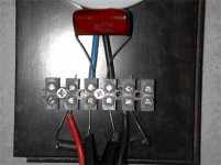
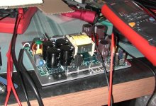
ackcheng said:This is how they are connected up
Long capacitor leads are hurting the efficiency of the filter.
Also a SMPS transformer should not buzz unless there is either a control loop instability problem, some current limiting is being triggered, or a low mains voltage condition is causing the PSU to operate open loop at maximum duty cycle. That's something worth checking.
In SMPS there is usually audible transformer noise with very low loads, but that's due to harmless pulse skipping.
As Eva pointed out, if you connect no load, the is some audible noise, due to the controller stopping the pulses from time to time in order to keep the voltage at the desired level. This is easily solved by drawing some mA from each rail (that's what the 2K7/2W resistors at each rails are for).
The transformer buzzing under load is not really a buzz, and definitely not due to instability in the feedback loop, as it is implemented with low loop gain and is unconditionally stable, nor to current limit (you can get much more than 440W from it, that's tested). The duty cycle is near max. at that power, however, and mains line variation can be appreciable ;-)
You all should hear it, the "buzzing" is very very low and I think Ackcheng simply commented about it as a side note.
Every transformer/inductor submitted to high current levels can buzz a bit, due to the windings vibrating a little bit around the core and its deformation due to magnetostriction. Even the cores of Class-D amplifiers sound when you output high power ;-)
Eva said:
Long capacitor leads are hurting the efficiency of the filter.
Also a SMPS transformer should not buzz unless there is either a control loop instability problem, some current limiting is being triggered, or a low mains voltage condition is causing the PSU to operate open loop at maximum duty cycle. That's something worth checking.
In SMPS there is usually audible transformer noise with very low loads, but that's due to harmless pulse skipping.
Yes, that was my first reaction too, make the wires to the cap as short as possible. You can also add like a 470uF cap or, that further smooths the ripple (did that with another SMPS I have).
Best regards
Gerrjan
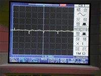
ackcheng said:now with the choke and 0.47uF after forming a pi filter
only 300mV amplitude.
Next will be a test on the UCD modules
If you want to see what it does with the UcD modules, then my advice is to do the following.
Connect the supply to the UcD module. With the scope, monitor the voltage over one of the 470uF caps on the UcD board. Do that with the UcD in standby mode. Then you will see that hardly any noise from the supply rails reached that 470uF cap (the UcD supply rail on board). The LC filter on the UcD board does a very good job keeping HF power supply rail noise out. If you turn the UcD on, you will see quite a lot of noise over those 470uF caps, this noise is induced by the UcD itself and is much bigger in amplitude then the noise from the SPS80. So any remaining noise from the SPS80 should be no issue at all.
Best regards
GErtjan
- Status
- This old topic is closed. If you want to reopen this topic, contact a moderator using the "Report Post" button.
- Home
- Amplifiers
- Class D
- testing of SPS80 SMPS