what's new is the top media player with a 2 bay notebook drive frame. it was quite a challenge to get the pi, its audio board and the disk frame in a box and have it 'make sense'.
In my builds, I have opted for maximum miniaturisation - given the constraints of the interconnect cables etc.
I did some even smaller builds, but they turned out to be impractical, since most of the clients use rather large and bulky interconnect and/or speaker cables - so I had to make the boxes a bit larger and leave ample space on the back for the connectors.
I've thought about making something like you did, but I'm planning to put everything into an old tape deck enclosure. That idea is still waiting to be implemented
")
And I'll go the same way you did (already have the necessary cabling): not expose RPi connectors directly, but use extension panel-mounted cabling. And yes, it was difficult to find those

And I'll go the same way you did (already have the necessary cabling): not expose RPi connectors directly, but use extension panel-mounted cabling. And yes, it was difficult to find those
the onboard ports are just not strain relieved enough for my liking. and while its a total hack to do what I did, its the 'right' thing to do if you HAVE to use existing things and not go fully custom (ie, making your own player board and not using a pi, etc etc).
how you approach a one-off build using existing parts is quite diff from doing a proper build that intends to see hundreds made from one set of plans I would never want to ship this to a customer, but for a one-off demo, sure, its fine for me
most people here on diyaudio are doing one-off builds, so this is ok.
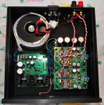
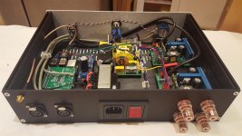
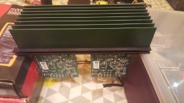
Here is a decent-looking but "failed" amp I built. The two amp modules are DUG-1 tpa3116 PBTL boards.
Power supply is a Sigma 11 configured for 18V. Transformer is an Antek AS-1220 (100VA 20V).
You can't see them in the pictures, but below the amp boards are two Jensen JT-11P-1 input transformers. The intent of using these was for DC-blocking and unbalanced to balanced conversion. I call this project "failed" because using these transformers created a hum. On its own, the hum was mild enough to be ignored, but when paired with my DAC, the hum was too much to bear.
Note that the DAC with any other amp produced no hum, and this amp with a different DAC did not increase the hum. Negative synergy?
At any rate, I've since removed the input transformers and installed DC-blocking caps on the amp boards. Now the amp is completely silent, with no trace of hum, regardless of what device it's connected to.
Attachments
Here is a decent-looking but "failed" amp I built. The two amp modules are DUG-1 tpa3116 PBTL boards.
Power supply is a Sigma 11 configured for 18V. Transformer is an Antek AS-1220 (100VA 20V).
You can't see them in the pictures, but below the amp boards are two Jensen JT-11P-1 input transformers. The intent of using these was for DC-blocking and unbalanced to balanced conversion. I call this project "failed" because using these transformers created a hum. On its own, the hum was mild enough to be ignored, but when paired with my DAC, the hum was too much to bear.
Note that the DAC with any other amp produced no hum, and this amp with a different DAC did not increase the hum. Negative synergy?
At any rate, I've since removed the input transformers and installed DC-blocking caps on the amp boards. Now the amp is completely silent, with no trace of hum, regardless of what device it's connected to.
A possible cause could be that the mains transformer stray field could be picked up by the input transformers due to the short distance between them....
+1A possible cause could be that the mains transformer stray field could be picked up by the input transformers due to the short distance between them....
I had the same problem when transformer was very close to the iput VAS stage on my headphone amplifier. Well it is not the same situation, but as said transformers do stray magnetic field and can be easily picked up by other components.
If you can try to use transformer with magnetic shield.
If you can try to use transformer with magnetic shield.
The Jensen JT-11P-1 are encased in mu-metal shielding.
A possible cause could be that the mains transformer stray field could be picked up by the input transformers due to the short distance between them....
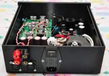
While trying to debug this I did move the power transformer out of the chassis, as far away as the secondary leads would allow (they used to be much longer than the picture shows, I later trimmed them down to size). At the same time, I also moved the input signal transformers out of the chassis (the other side of the chassis from the power transformer). The stock leads on the signal transformers are also pretty long, so I had a good two feet between power and signal transformers (with the chassis in between). That didn't solve the problem.
TPA 3116 with Sure Electronics board
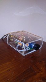
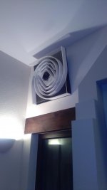
Built a nice enclosure for this board.
Plexiglas with a curved top. Amazing what you can do in your home oven.
Upgraded the caps with Panasonic Oscon, and added an Alps pot and on/off switch. The sides of the curved top don't come down far enough, so I'll probably do Mark2 version of that.
Very happy with this...
Goes nicely (and sounds nice) with my Cornu speakers with a plexiglass front.
Attachments
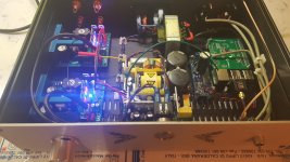
thanks - I did them myself. I could upload the pdf of the layout and anyone who has a lasercutter could do it. I use 1/8" acrylic and a simple 'tabbed box' style (that's what its referred to).
cost is not much, for materials. my local shop sells 18"x24" sheets for about $15 each. you can get most of a full box from that one sheet. since I use black and clear, the clear is only for the top (to be fancy) and so I need 2 sheets; but I think the whole box could be done with just 1 sheet.
I've tweaked the box a bit so maybe I'll upload one more photo and then its pdf design file at the same time.
I found some nice tie-downs while browsing on amazon and they help clean up the loose wiring. I'll add a link to those, too, since they are cheap and they really make the inside look a lot less hacky.
plastic offers no emi/rfi protection and it offers no safety protection, in that there is no ground to connect the 'green wire' to from the ac outlet. if I could do metal easily and cheaply, I would; but I also tend to try lots of variations and using metal for that would be expensive. plastic lets you try various things and if it does not work out, its not a huge loss (again, $15 a sheet plus your time).
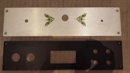
finally, the labeling is on-the-cheap, as well. secret is to etch lettering deeply into the plastic (2 etch runs), then leave the paper masking on, drip and force some white acrylic paint into the voids, press it in and remove all bubbles, let it set 10 minutes, peel paper backing and clean up any spill-overs. if you use shiny plastic instead of matte, the acrylic white paint comes off with only fingernail pressure and that process leaves no marks. its not the best lettering process, but its HELLA CHEAP (lol) and its kind of fun, in an arts craftsy way (you get the paint at a hobby arts store in small bottles).
cost is not much, for materials. my local shop sells 18"x24" sheets for about $15 each. you can get most of a full box from that one sheet. since I use black and clear, the clear is only for the top (to be fancy) and so I need 2 sheets; but I think the whole box could be done with just 1 sheet.
I've tweaked the box a bit so maybe I'll upload one more photo and then its pdf design file at the same time.
I found some nice tie-downs while browsing on amazon and they help clean up the loose wiring. I'll add a link to those, too, since they are cheap and they really make the inside look a lot less hacky.
plastic offers no emi/rfi protection and it offers no safety protection, in that there is no ground to connect the 'green wire' to from the ac outlet. if I could do metal easily and cheaply, I would; but I also tend to try lots of variations and using metal for that would be expensive. plastic lets you try various things and if it does not work out, its not a huge loss (again, $15 a sheet plus your time).
finally, the labeling is on-the-cheap, as well. secret is to etch lettering deeply into the plastic (2 etch runs), then leave the paper masking on, drip and force some white acrylic paint into the voids, press it in and remove all bubbles, let it set 10 minutes, peel paper backing and clean up any spill-overs. if you use shiny plastic instead of matte, the acrylic white paint comes off with only fingernail pressure and that process leaves no marks. its not the best lettering process, but its HELLA CHEAP (lol) and its kind of fun, in an arts craftsy way (you get the paint at a hobby arts store in small bottles).
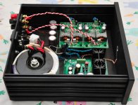
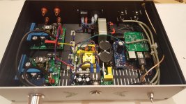
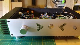
Network attached UCD400 Class D
Thanks to everyone who held my hand through this project, particularly with respect to the Pi Power supply and the selector switch. Oh and thanks also to Jeff Willing for kindly offering his time with CAD.
Most of this was painting by numbers and time spent trying to understand and researching what I was actually painting! Built a tube pre and power amp with the help this forum previously and a few other kitchen projects.
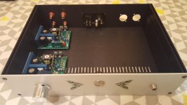
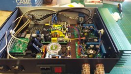
So, two UCD400 modules and a SMPS 400 from Hypex, a Raspberry Pi with Moode running, an LDO TPS based regulated supply for the Pi (Thanks Ales, Mravlca), an Alps 10K pot, a DP4T selector switch and a beautiful LED lit power switch from Schruter.
A few issues with the Pi supply over heating initially which is why you may notice the transformer change (which improved but not solved) and the addition of an 8V pre reg circuit which I intend to loose once I have a suitable transformer.
The sound.... very nice indeed... close to my ecl86 baby huey tube amp but with tighter bass which I enjoy but more clinical in the mids / tops which I don't enjoy as much as the tube amp.
Hypex recommended a preamp for the Pi so I had a simple NE5534 buffer to put between Pi and UCD but I ran out of space and time and the sound for the network player was very good without it (Would definitely be better with it though).
The switch selects between Airplay (Pi / moode and Unbalanced) and XLR Balanced. The pot only controls volume for the Pi.
Chassis by HIFI2000.... obvioulsy
Thanks to everyone who held my hand through this project, particularly with respect to the Pi Power supply and the selector switch. Oh and thanks also to Jeff Willing for kindly offering his time with CAD.
Most of this was painting by numbers and time spent trying to understand and researching what I was actually painting! Built a tube pre and power amp with the help this forum previously and a few other kitchen projects.
So, two UCD400 modules and a SMPS 400 from Hypex, a Raspberry Pi with Moode running, an LDO TPS based regulated supply for the Pi (Thanks Ales, Mravlca), an Alps 10K pot, a DP4T selector switch and a beautiful LED lit power switch from Schruter.
A few issues with the Pi supply over heating initially which is why you may notice the transformer change (which improved but not solved) and the addition of an 8V pre reg circuit which I intend to loose once I have a suitable transformer.
The sound.... very nice indeed... close to my ecl86 baby huey tube amp but with tighter bass which I enjoy but more clinical in the mids / tops which I don't enjoy as much as the tube amp.
Hypex recommended a preamp for the Pi so I had a simple NE5534 buffer to put between Pi and UCD but I ran out of space and time and the sound for the network player was very good without it (Would definitely be better with it though).
The switch selects between Airplay (Pi / moode and Unbalanced) and XLR Balanced. The pot only controls volume for the Pi.
Chassis by HIFI2000.... obvioulsy
Attachments
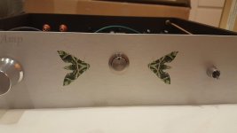

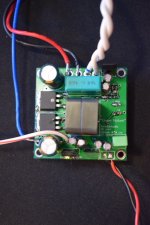
Green Nature v4
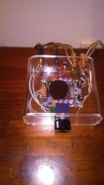
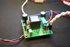
Latest version of my 5x5 cm 100W self osc amp. pre and post-filter fb.
Still based on OP275, MAX913, LM5401 and IRFS5615
From v3 to v4 I changed the 3 transistors for the voltage regs to BD139/BD140, to lift some heat away from the PCB ..... on version 3 they heated up everything on the board .....
The PSU transistors still get hot of course, but now placed in a way where they get more air flow ... and also can be mounted with a small heatsink or down to a alu back plate .... but running ok on +-40VDC
Attachments
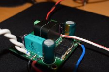
Hmmm, after running v4 for a little time, I must admit that the board/coil is still heating up. I know it is not the coil, as I have previously tried mounting it off board, so only thing left is the driver (LM5401) mounted just beneath the coil on the other side of the pcb.
It is not critical, but could have been a little better. Will try to lift the coil a few mm to get a bit of air beneath. .... still learning
It is not critical, but could have been a little better. Will try to lift the coil a few mm to get a bit of air beneath. .... still learning
Thanks
Only using it for a small office sub yet.
Next will be one more channel for stereo and using a Connexelectronic 240W SMPS.
.. So I'll get back with sonic impressions later
PS. the heat is not a big problem. But limiting the design to 5x5cm makes it more of a challenge
Only using it for a small office sub yet.
Next will be one more channel for stereo and using a Connexelectronic 240W SMPS.
.. So I'll get back with sonic impressions later
PS. the heat is not a big problem. But limiting the design to 5x5cm makes it more of a challenge
I think I should have posted it here. interesting solid aluminum Ncore build: link
An externally hosted image should be here but it was not working when we last tested it.
An externally hosted image should be here but it was not working when we last tested it.
An externally hosted image should be here but it was not working when we last tested it.
An externally hosted image should be here but it was not working when we last tested it.
An externally hosted image should be here but it was not working when we last tested it.
An externally hosted image should be here but it was not working when we last tested it.
- Home
- Amplifiers
- Class D
- Class D Amp Photo Gallery