Lars Clausen said:As a comment for the ongoing discussion about foil coils, here is a comparation for post #52, it is the saturation curve for a 30uH foil coil, on RM10.

and this is not 10Amps per division?

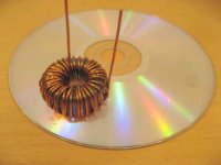
Think I read somewhere that a method of reducing the self capacity on a toroid is to wind all the way around in a single layer, and thereafter wind back on half the torid to end with the terminals on "opposite" sides of the core! (see picture of my newly would coil)
Can anyone confirm the truth in this??
(using 40 turns of 1 mm wire on a Micrometal T157-2 core)
Can anyone confirm the truth in this??
(using 40 turns of 1 mm wire on a Micrometal T157-2 core)
Attachments
It might be interesting to add the choice of output filter capacitor to the discussion. How do capacitor parameters relate to performance? Something besides logic makes me want to use Polypropylene capacitors, but I would like to know more about how capacitor non-ideal behaviour affects the filter performance and the loop behaviour in a UcD amplifier before I settle on a final design.
(yes, I am too lazy to do the math I learned many years ago)
(yes, I am too lazy to do the math I learned many years ago
)Baldin said:Think I read somewhere that a method of reducing the self capacity on a toroid is to wind all the way around in a single layer, and thereafter wind back on half the torid to end with the terminals on "opposite" sides of the core! (see picture of my newly would coil)
Can anyone confirm the truth in this??
(using 40 turns of 1 mm wire on a Micrometal T157-2 core)
Maybe you'd want to go through the past posts and find that link to the place that talks about it. I remember posting a link a while ago.
Soongsc:
Didn't find the post you are talking about!
Two articles on coils and capacitance:
http://powerelectronics.com/mag/508PET22.pdf
http://focus.ti.com/lit/ml/slup125/slup125.pdf
Didn't find the post you are talking about!
Two articles on coils and capacitance:
http://powerelectronics.com/mag/508PET22.pdf
http://focus.ti.com/lit/ml/slup125/slup125.pdf
Baldin said:Soongsc:
Didn't find the post you are talking about!
Two articles on coils and capacitance:
http://powerelectronics.com/mag/508PET22.pdf
http://focus.ti.com/lit/ml/slup125/slup125.pdf
http://www.diyaudio.com/forums/showthread.php?postid=1023525#post1023525
This is the post that links to another thread also talking about coils.
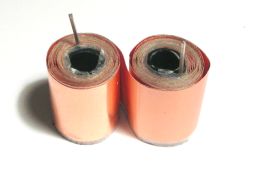
Not so easy, in the picture I used a common adhesive tape for insulation. I must get the right tape for the right temperatures, then I have to find the right plastic or wood core size. Finally, with trial and errors, I must find the 10uH I need: with this coil you have to now the exact copper foil lenght needed, because the two cores are to be coiled from ends to center. Or I could wind one coil to get 5uH, then cut a foil with two times the lenght needed for 5uH?
Like this?
Exactly !!!
Even being just a prototype your coil looks good !!!
Or I could wind one coil to get 5uH, then cut a foil with two times the lenght needed for 5uH?
That should indeed work as an approximation. Inductance is proportional to the square of the amount of windings but also to 1/length. With two coils put together this way you'll get twice the windings and twice the effective length which will give you twice the inductance of one coil. This is of course a simplification but you will be quite close IMO.
Regards
Charles
Maybe we should aso discuss placement of the coils.
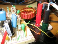
I'm workng on a muck up for a single ended design, and have a filter of 20uH/1uF on the output. The coil is a Micrometal T157-2 as described in a earlier post.
I think the coil produces quite a lot of noise that couples into the amp!
Placing a finger on the coil reduces the noise a lot.
Moving it around also changes the level of noise.
Question is how should it be placed on a final PCB
From paper by Bruno on Hypex web, it can be read that Toroids are to be avoided (don't really believe that), but also that it is important that the coils are placed flat on the board with a sufficient ground layer under.
I tried to take a pice of grounded alu foil and placed it nea the coil, but it seems to have almost no effect.
Maybe it's more the 2" of wire thet is connecting the coil more that the coil.
I would guess that the coil should be placed as close to the mosfets as possible.
Attachments
Despite what people says, toroids actually produce very strong stray magnetic fields in the near field and in all planes, cancellation is only achieved in the far field. E cores are easier to handle because they unly produce stray magnetic fields in a single plane which may be chosen for minimum interference.
Try to place the toroid 20cm away from the breadboards.
Try to place the toroid 20cm away from the breadboards.
Eva said:Despite what people says, toroids actually produce very strong stray magnetic fields in the near field and in all planes, cancellation is only achieved in the far field. E cores are easier to handle because they unly produce stray magnetic fields in a single plane which may be chosen for minimum interference.
Try to place the toroid 20cm away from the breadboards.
Hi Eva,
Could you be more specific about the result yourself...what would be the resultant effect....
K a n w a r
- Status
- This old topic is closed. If you want to reopen this topic, contact a moderator using the "Report Post" button.
- Home
- Amplifiers
- Class D
- Design of output inductor for class D amplifier