What do folks make of this new class D integrated solution?
http://www.ti.com/corp/docs/landing/tas5261/index.htm?DCMP=hpa_amp_tas5261&HQS=Other+EM+tas5261-em
Certainly looks neat and offers respectable performance.
Any products confirmed as using these yet? And do you think its of any interest to the DIY market?
http://www.ti.com/corp/docs/landing/tas5261/index.htm?DCMP=hpa_amp_tas5261&HQS=Other+EM+tas5261-em
Certainly looks neat and offers respectable performance.
Any products confirmed as using these yet? And do you think its of any interest to the DIY market?
ssanmor said:Mmmm.
Max power established at a THD of 10%... very professional
Perhaps Hypex, LCAudio and us, Coldamp, should rate our products at 50% higher power.
Bit out of context that.
• 125 W into 8 Ω at <0.09% THD+N
• 220 W into 6 Ω at 10% THD+N
• 315 W into 4 Ω at 10% THD+N
The 125w into 8ohm and less than 0.1% isn't bad at all for an integrated solution. Certainly better than the Gainclones and competitive with the higher power t-amps.
Yes, that's right, 0.1% at rated power is quite ok, but I was only saying that specifying 300w at 10% is next to useless and a bit tricky (marketing stuff, anyway).
They would have seemed much more serious if they had said 180W at 1% 4 ohm (it must be something like that). Nothing more...
They would have seemed much more serious if they had said 180W at 1% 4 ohm (it must be something like that). Nothing more...
ShinOBIWAN said:Any products confirmed as using these yet? And do you think its of any interest to the DIY market? [/B]
I've ordered some samples, if I can solder these, I'll report back here on the result. Should be interesting.
SmellOfPoo said:@ericallan: I´ve ordered some samples too. Obviously PWM input is needed; did you figure out how to do that?
This page might help:
http://homepages.which.net/~paul.hills/Circuits/PwmGenerators/PwmGenerators.html
You can generate a PWM signal from an audio signal using a simple 555 timer. You can either figure out how to do it from the datasheets or search the web for a schematic.
Do you have an evaluation board or have you designed a board for this chip?
ericallan said:I've ordered some samples, if I can solder these, I'll report back here on the result. Should be interesting.
Do you have an evaluation board or have you designed a board for this chip?
BWRX said:You can generate a PWM signal from an audio signal using a simple 555 timer. You can either figure out how to do it from the datasheets or search the web for a schematic.
Do you have an evaluation board or have you designed a board for this chip?
I'm wondering if this might do the trick:
http://shop.dataip.co.uk/products.html?prodid=81
An externally hosted image should be here but it was not working when we last tested it.
the sweet(er) spot?
" ... can drive 125W, 8 ?, at less than 0.09% THD+N with 95% efficiency. ..." From: http://www.ti.com/corp/docs/landing/tas5261/index.htm
Looks like their standard model is designed strictly for 8 ohms, 6 or 4 ohm loads need not apply ... or keep a lid on it, power wise.
" ...
• Short-circuit protection
• Over-current protection
• Undervoltage protection
• PWM activity detector for loss of PWM input signal ..."
Add to this list:
• Over 125W limiting ...
I don't know how to make it work with this input stage, since I never did any Digital Amp... If it's able to be a 300W output stage, why they don't make a single chip solution ?
I think this is a wonderful chip !! 95% of efficiency is something just incredble ! Using it on a 8Ohms Load at full power, it will only dissipate 6,25W of heat
Anyway, what do I need for the input ? I mean, what chips and how to connect to have a complete amplifier that I can conect my iPod / Discman on it ?
I'm building a pair of Beyma Speakers, with a 100W RMS Woofer 10" 8Ohms, and I should make it self powered, as heat is a big problem I found this chip great. Does it sound good?
Regards,
Fernando
-_nando-_ said:Does it sound good?
Is that important with 315 W into 4 Ω at 10% THD+N ?
Need a little help here:
... I noticed that the pdf file docs & graphs on this chip indicate that it might be quite good as an element in a bi-amped or tri-amped system as well as a mono-block sub woofer amp. ( http://focus.ti.com/lit/ds/sles188/sles188.pdf ... pp. 7 through 13 ... graphs on pp. 11, 12, 13 )
THD limits ?
100W into 8 ohms = PS rail voltage +/- 45 VDC (THD~= 0.07%)
~75W into 6 ohms = PS rail voltage +/- 25 VDC (THD ~=0.07%)
( THD goes all to heck into 4 ohms >>= 0.1 above 3W = )
Comments please? Got ideas to improve on this? Any idea if this is worth doing?
(I have two samples coming and intend to get together some boards if anyone is interested.)
....
-_nando-_ " ... I'll drive 8 Ohms Hi-Fi speakers, but I believe that it sound better than a Gainclone, am I right? ..."
Not really, I have seen higher power Gainclones with better THD specs.
jean-paul: " ... Is that important with 315 W into 4 ½ at 10% THD+N ? ..."
Yes, to me any way. I tend to dis any amp with worse THD than about 0.1% = bad work arounds or bad design / execution = good for nothing except maybe sub-woofer drivers.
-_nando-_ " ... 95% of efficiency is something just incredble ! ..."
Yes, and that is what may make this chip worthwhile.
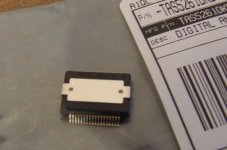
" ... 'm wondering if this might do the trick: http://shop.dataip.co.uk/products.html?prodid=81 ... board pic ..."
Probably would work OK = 36 pin surface mount chip, so there would be some extra room on the baord for other stuff.
BWRX: " ... I really like the pin out for the power and output side of that chip. The input side isn't too shabby either. What's up with that noise amplitude graph in figure 9? ..." (on page 13 of the pdf file.)
My guess is that the graph is frequency = 1k Htz increments = ?? If the spike is really around 1K Htz, then my concern would be that point as well as around 2 to 20 Htz ... possible the 1K spike will have to be delt with at the power supply.
One reason for this may be: TI indicates a "split" or "Half Bridge" PS (page 4 and elsewhere) .. ?? I guess this means two half bridge rectifiers, one for each power rail (??). Any ideas or clarification here would be appreciated.
... I noticed that the pdf file docs & graphs on this chip indicate that it might be quite good as an element in a bi-amped or tri-amped system as well as a mono-block sub woofer amp. ( http://focus.ti.com/lit/ds/sles188/sles188.pdf ... pp. 7 through 13 ... graphs on pp. 11, 12, 13 )
THD limits ?
100W into 8 ohms = PS rail voltage +/- 45 VDC (THD~= 0.07%)
~75W into 6 ohms = PS rail voltage +/- 25 VDC (THD ~=0.07%)
( THD goes all to heck into 4 ohms >>= 0.1 above 3W =
)Comments please? Got ideas to improve on this? Any idea if this is worth doing?
(I have two samples coming and intend to get together some boards if anyone is interested.)
....
-_nando-_ " ... I'll drive 8 Ohms Hi-Fi speakers, but I believe that it sound better than a Gainclone, am I right? ..."
Not really, I have seen higher power Gainclones with better THD specs.
jean-paul: " ... Is that important with 315 W into 4 ½ at 10% THD+N ? ..."
Yes, to me any way. I tend to dis any amp with worse THD than about 0.1% = bad work arounds or bad design / execution = good for nothing except maybe sub-woofer drivers.
-_nando-_ " ... 95% of efficiency is something just incredble ! ..."
Yes, and that is what may make this chip worthwhile.
" ... 'm wondering if this might do the trick: http://shop.dataip.co.uk/products.html?prodid=81 ... board pic ..."
Probably would work OK = 36 pin surface mount chip, so there would be some extra room on the baord for other stuff.
BWRX: " ... I really like the pin out for the power and output side of that chip. The input side isn't too shabby either. What's up with that noise amplitude graph in figure 9? ..." (on page 13 of the pdf file.)
My guess is that the graph is frequency = 1k Htz increments = ?? If the spike is really around 1K Htz, then my concern would be that point as well as around 2 to 20 Htz ... possible the 1K spike will have to be delt with at the power supply.
One reason for this may be: TI indicates a "split" or "Half Bridge" PS (page 4 and elsewhere) .. ?? I guess this means two half bridge rectifiers, one for each power rail (??). Any ideas or clarification here would be appreciated.
That PC board layout in the docs ...
... is probably not correct. It looks like the docs refer to a 36 pin surface mount chip and that board looks like it is designed for a 16 / 18 pin chip w/ heat sink mount ... ??
" " ... 'm wondering if this might do the trick: http://shop.dataip.co.uk/products.html?prodid=81 ... board pic ..."
I won't know for sure until the chips get here ...
Later
- Status
- This old topic is closed. If you want to reopen this topic, contact a moderator using the "Report Post" button.
- Home
- Amplifiers
- Class D
- Texas Instruments TAS5261