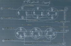
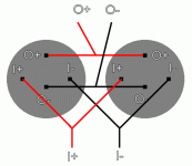
Yeah I see that question alot. I also provided a schematic before which showed a basic connection, but it's truly not the way to do it for best results. Here is how it's really done. Introducing, the T-Z supply~! (So good I had to name it)
What you can expect from it (and why):
-Ultra fast, insanely dynamic response (T-network goodness)
-Deeeep rich black-hole like noise floor (T-cap /UcD goodness)
-Super fine, coherent resolution extending to the most minute microdynamics (T-cap/UcD goodness)
-Low interfereance between channels (twisting, minimal loop area goodness, full dual ground goodness)
-All the thunder of parallel caps
-All the coherency of non parallel caps
Have you ever heard people say, or experienced yourself, that parallel caps don't sound as good? It's because they weren't wired right. So this "Z" method is used to equalize parasitic inductance and therefore current flow. It is all that's required to make it happen, and applies equally for normal caps as it does to T-networks.
Additional tips.
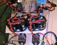
-Loop area must remain small. That means twisting everywhere. It also means you'll have to do some real work to wire the T-networks, no big lazy, looping wire connections between terminals. Rather, set up your T-networks that you need paralleled so all terminals face the same way as the schematic, then you'll see you can just give them a "bit" of a twist to get them off center, and you'll then have just enough room to lay the wires flat across the tops of the caps and snake them between terminals without any real bending. The goal is a straight wire run from terminal to terminal.
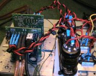
-To avoid burning your caps, melting them with solder, the iron, the hot wire, making a mess of them with flux all over..
After you have the caps situated properly, tiewrap them down, press a doubled up layer (or more) of tinfoil over the terminals. I also used a layer of plane old paper on top of that, because I didn't want tinfoil stuck to my solder joints. You can use some toothpics, or whatever makes sense, as spacers under the wires to ensure you can easily rip out the tin/paper after. Otherwise it can be a real pain to remove, and you'll be there for awhile! So this will protect your caps, but don't get your terminals confused because you wont' be able to see them anymore until the job is done.
-Group and twist the outputs as shown on the schematic. That will leave you with two pairs of wires (per amp), which you can also twist together, or simply tiewrap them together to ensure minimal loop area.
-This 4 pole version is only to be used with dual bridge rectifiers, connection of which is not the topic of this post. Anything less will not gain you the full benefits of T-network goodness.
-Don't even think of trying this with solide core, it really doesn't even sound as good if you ask me. Go with either stranded, or all out, with Litz. Litz is what I used. It took alot of time trimming, tinning, and filing for exact fit. _Take your time_!
-You'll note I actually used 2X Litz between terminals, with even a single twist in the middle. This was uncalled for, and made the work alot harder, it was merely an exercise in extreme overkill on my part. In some places, I like a little overkill, don't feel it is a requirement, I don't even recommend it.
If this supply falls short of your expectations, you probably messed up your grounding elsewhere, or you amp isn't good enough.
*I do not advocate the use of Jensen caps over BHC T-networks. I have Jensen caps, I prefer BHC. Use what you can get your hands on, they're still pretty close.
*Please don't email me asking for complete schematics or to design your power supply for you, unless you're willing to make it worth my while $. This is gift enough, I think.
Chris
What you can expect from it (and why):
-Ultra fast, insanely dynamic response (T-network goodness)
-Deeeep rich black-hole like noise floor (T-cap /UcD goodness)
-Super fine, coherent resolution extending to the most minute microdynamics (T-cap/UcD goodness)
-Low interfereance between channels (twisting, minimal loop area goodness, full dual ground goodness)
-All the thunder of parallel caps
-All the coherency of non parallel caps
Have you ever heard people say, or experienced yourself, that parallel caps don't sound as good? It's because they weren't wired right. So this "Z" method is used to equalize parasitic inductance and therefore current flow. It is all that's required to make it happen, and applies equally for normal caps as it does to T-networks.
Additional tips.
-Loop area must remain small. That means twisting everywhere. It also means you'll have to do some real work to wire the T-networks, no big lazy, looping wire connections between terminals. Rather, set up your T-networks that you need paralleled so all terminals face the same way as the schematic, then you'll see you can just give them a "bit" of a twist to get them off center, and you'll then have just enough room to lay the wires flat across the tops of the caps and snake them between terminals without any real bending. The goal is a straight wire run from terminal to terminal.
-To avoid burning your caps, melting them with solder, the iron, the hot wire, making a mess of them with flux all over..
After you have the caps situated properly, tiewrap them down, press a doubled up layer (or more) of tinfoil over the terminals. I also used a layer of plane old paper on top of that, because I didn't want tinfoil stuck to my solder joints. You can use some toothpics, or whatever makes sense, as spacers under the wires to ensure you can easily rip out the tin/paper after. Otherwise it can be a real pain to remove, and you'll be there for awhile! So this will protect your caps, but don't get your terminals confused because you wont' be able to see them anymore until the job is done.
-Group and twist the outputs as shown on the schematic. That will leave you with two pairs of wires (per amp), which you can also twist together, or simply tiewrap them together to ensure minimal loop area.
-This 4 pole version is only to be used with dual bridge rectifiers, connection of which is not the topic of this post. Anything less will not gain you the full benefits of T-network goodness.
-Don't even think of trying this with solide core, it really doesn't even sound as good if you ask me. Go with either stranded, or all out, with Litz. Litz is what I used. It took alot of time trimming, tinning, and filing for exact fit. _Take your time_!
-You'll note I actually used 2X Litz between terminals, with even a single twist in the middle. This was uncalled for, and made the work alot harder, it was merely an exercise in extreme overkill on my part. In some places, I like a little overkill, don't feel it is a requirement, I don't even recommend it.
If this supply falls short of your expectations, you probably messed up your grounding elsewhere, or you amp isn't good enough.
*I do not advocate the use of Jensen caps over BHC T-networks. I have Jensen caps, I prefer BHC. Use what you can get your hands on, they're still pretty close.
*Please don't email me asking for complete schematics or to design your power supply for you, unless you're willing to make it worth my while $. This is gift enough, I think.
Chris
Attachments
angchuck said:Hi Chris,
I am curious about the - in into the caps, why the last cap first? Or am i being redundent?
Chuck
This is key to the "Z" technique of equalizing parasitic inductance. It should be wired exactly this way.
You can see the inputs are actually across the bank of caps, with the outputs on the opposing end. This forces the charging/discharging current flow to see the same parasitic inductance.
The alternative is both inputs are connected to the same cap, and outputs taken at the opposing end across the same cap.
What you'd have then is that the first cap in the chain see's the least inductance so it takes a big gulp of current, then the charging currents see more inductance to the second cap, and get a smaller gulp...and so on. They'd also discharge in the same fashion, which does some ugly things to the coherency of the sound, kind of blurrs out your microdetail and then some.
It's imperative it be wired this way, or you won't get the coherency I mentioned. Parallel caps can sound exactly as good (only better due to lower ESR) as a single cap if you wire it exactly as shown.
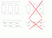
I'll try and post another little diagram I have from someone that better demonstrates the technique of equalized parasitics on standard caps, it should help you visualize things better.
I hope that answered your question.
That's basically how I did it, you can't just simply parallel them as you lose all the benefits, the PCB pictured below shows how this translates to an actual (double-sided in this case) PCB.


Best regards,
Sander Sassen
http://www.hardwareanalysis.com
Best regards,
Sander Sassen
http://www.hardwareanalysis.com
Since the PCB is double-sided, hence the other half is blocked from view, the below image might be more illustrative.

Best regards,
Sander Sassen
http://www.hardwareanalysis.com
Best regards,
Sander Sassen
http://www.hardwareanalysis.com
Hi Sander,
From what I can see, very nice layout.
However, your method of // the T-nets is unfortunatly different from mine, and not the best method for audio, as the ESR of the caps is added with each additional cap in //. Mine maintains the division of ESR as you'd normally get by paralleling caps.
If you have a look at the Jensen white paper, you'll see they don't recommend your method for audio, due to the higher ESR.
It also doesn't seem to make use of equalized parasitics.
Your method of snubbing the rectifiers can also pass along HF noise. I just use a single R+C across each bridge.
I hope you give the method I've shown a try and report the difference.
Best Regards,
Chris
Hi Chris,
This gave the best results in my experience, noise was down a full 3dB and according to BHC this was indeed the correct way of using more than one T-net capacitor per rail. Mind you, I'm not after lowering the ESR, I am however after making sure less rectifier and other noise propagates into the rails.
Best regards,
Sander Sassen
http://www.hardwareanalysis.com
classd4sure said:Here you go, this might help fill in a blank or two.
Artwork courtesy of Poobah.
My schematic applies this technique of equalized parasitic inductance to t-network caps, that's why it's important to wire exactly as shown.
Yes, somehow, this picture came to my mind when you were explaining this theory to me.
Thank
")
Parasitic inductance
Wouldn't it be best to have input and output between the two caps, instead of on either side? Although not necessarily applicable to this, it would look more like paralelling the caps, whereas your method would be putting them in series. (Only as far as wiring goes, of course. Electrically, both options are paralell.)
Wouldn't it be best to have input and output between the two caps, instead of on either side? Although not necessarily applicable to this, it would look more like paralelling the caps, whereas your method would be putting them in series. (Only as far as wiring goes, of course. Electrically, both options are paralell.)
Re: Parasitic inductance
Absolutely not.
I guess it depends if your concern is with aesthetics or function. My method ensures best possible function by forcing both charging and discharging currents to see equalized parasitic inductance. So functionally the two aren't equivalent at all.
novec said:Wouldn't it be best to have input and output between the two caps, instead of on either side? Although not necessarily applicable to this, it would look more like paralelling the caps, whereas your method would be putting them in series. (Only as far as wiring goes, of course. Electrically, both options are paralell.)
Absolutely not.
I guess it depends if your concern is with aesthetics or function. My method ensures best possible function by forcing both charging and discharging currents to see equalized parasitic inductance. So functionally the two aren't equivalent at all.
Thanks, that answered my question. My logical, but uneducated brain just thought a center tap would be best (attached image). Whether I make myself a PCB or just go for wires, neither connection is more difficult.
BTW, do you have any extra T-nets? I need 12
BTW, do you have any extra T-nets? I need 12
Attachments
Glad it helped. Had you seen my original schematic that I mentioned in the first post of this thread, it was done very much that way, so I speak from experience when I say it's just not as functional.
Yeap, I have a crate of Jensen's and two crates of BHC's. Sold individually, 200 a pop I wish.
Hey if you're so inclined, try both methods and see which you end up favoring, I'd love to hear the results.
Yeap, I have a crate of Jensen's and two crates of BHC's. Sold individually, 200 a pop
I wish. Hey if you're so inclined, try both methods and see which you end up favoring, I'd love to hear the results.
- Status
- This old topic is closed. If you want to reopen this topic, contact a moderator using the "Report Post" button.
- Home
- Amplifiers
- Class D
- How do I parallel T networks?