Hi
Wow first time of-line, full bridge (is it?), 1.5kw, and my personal best that you use toroid. I would like to know everything about it. My first try was with ETD44@ 50kHz, unregulated, did put out 550w and I also plan to have PFC just for the same reason as you do, too big caps on input.
Wow first time of-line, full bridge (is it?), 1.5kw, and my personal best that you use toroid. I would like to know everything about it. My first try was with ETD44@ 50kHz, unregulated, did put out 550w and I also plan to have PFC just for the same reason as you do, too big caps on input.
That might be beating between smps and amp. I didn't have any measureble ripple, just 100Hz from mains, but I didn't connect amp as load but resistorsThe sum of power supply ripple and the amp ripple at voltage buses is really a mess
No, it´s really half-bridge, 2 irfp in parallel at each side.
I have some knowledge on smps design (push-pull battery powered) so that the things ran more easily than I supposed for first time.
It´s a little "hard" for a half-bridge design, I know, but it will not be used at continuos levels. I´m really curios if it will reach this level of power.
I like toroidals. Another PITA was winding it using triple insulation. But it´s working well.
I tested it at 500w continuous at output during one hour. No problems at all.
BTW, the gate driver and current sensor are toroidals too.
Regards,
")
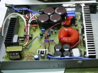
I used a 62mm toroidal core and there is current limiting (functional but not enabled yet - I will enable it after full power tests).
Since it is a 140VDC design, I put a bunch of 220v/200w bulbs in order to drain more or less 3A from the power supply. Used sunglasses to adjust this gadget....
It is an earlier photo of the prototype. I used a large pcb mounting because I planned to fit it exactly in the chassis and, as a first design, I was very conservative on building it.
Best regards,
Attachments
Hi
This is all in 1HE casing, right? I could say what happened to trafo, but I hope you will tell me what you did, some kind of insulation, or maybe that wires don't move. How did you winded it, how many turns/wires used? What is DC voltage on output, can you set it? I'm asking this because I'm not sure if you use your amp with 70v or you use it with lower value now. And one more thing is that +/-70V or just 70v(like +/-35v)
If I can just say, if you did use coupled output inductor, it would be much better if you would use toroid for that too.
I did it a year ago, but let me see if I remember right:
This is all in 1HE casing, and I have an EE core that fits ok for it too. But I like toroidals.
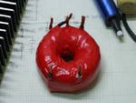
The insulation was done using poliester tape for transformers and a red high voltage 3m tape. the primary first and the secondaries after that in a bifilar wound. Not the best considering coupling but easier to wind. the end of the wires were isolated using thermal material. And everithing was glued using high voltage silicon adhesive. It´s solid rock mounting and after lots of tests appears to be OK.
The wires are 18awg in parallel. I used the formulae of McLyman´s book (excellent books from this author). I don´t remember the values, but it´s easy to retrieve, if necessary. They are in some notepad here, elsewhere.
I´m using a linear regulated power supply for 35vdc tests and this smps for 70vdc tests, both symmetrical.
And, yes, the toroidal core for the output coupled inductor would be much better, but I don´t have them available easily here in my country for iron powder or other similar material. Just ferrite ones. It is a coupled inductor using pot-core gapped ferrite.
The number 2 toroidal output inductor core I bought a year ago when travelling abroad. But even for it I will use a gapped pot-core after final adjusts of the amp.
Best regards,
This is all in 1HE casing, and I have an EE core that fits ok for it too. But I like toroidals.
The insulation was done using poliester tape for transformers and a red high voltage 3m tape. the primary first and the secondaries after that in a bifilar wound. Not the best considering coupling but easier to wind. the end of the wires were isolated using thermal material. And everithing was glued using high voltage silicon adhesive. It´s solid rock mounting and after lots of tests appears to be OK.
The wires are 18awg in parallel. I used the formulae of McLyman´s book (excellent books from this author). I don´t remember the values, but it´s easy to retrieve, if necessary. They are in some notepad here, elsewhere.
I´m using a linear regulated power supply for 35vdc tests and this smps for 70vdc tests, both symmetrical.
And, yes, the toroidal core for the output coupled inductor would be much better, but I don´t have them available easily here in my country for iron powder or other similar material. Just ferrite ones. It is a coupled inductor using pot-core gapped ferrite.
The number 2 toroidal output inductor core I bought a year ago when travelling abroad. But even for it I will use a gapped pot-core after final adjusts of the amp.
Best regards,
Hi
If it is not too much trouble to find values. It would help me see/compare your test with my. We both did it at ~500w but the thing is that my is +/-35Vdc idle, but goes down to +/-22Vdc at that power. Thats why I would like to know number of turns and if possible voltage at idle and 500w so I can compare them with my.
Do you have any info for your trafo?
Hi
Huh voltage drop at output at full load, that I didn't use as there wasn't need from me to do that. I would say that it would drop to min of +/-30Vdc since unregulated and for min input 200Vac, but that isn't important since this is unregulated for now and if input voltage is lower so is output and I see this as false operation.
Here is pic of trafo, still a lot of room for windings
http://2ner.angelcities.com/slike/SmpsHB.jpg
- Status
- This old topic is closed. If you want to reopen this topic, contact a moderator using the "Report Post" button.
- Home
- Amplifiers
- Class D
- Philips UCD application note