Or a better low VCEsat (biss) transistor such as PBSS5140T or 5240T or similar transistors would be an option.
PBSS5240T pdf, PBSS5240T description, PBSS5240T datasheets, PBSS5240T view ::: ALLDATASHEET :::
2N3906 or bc639 will these work in totem pole and gate drive they are non smd to-92 package

hi whortless i have made the below schema but q13,14,3 & 21 plus the aux +12v section fails vltg is ir2110 smps +/- 55vlts but my outputs fets are o.k . what is my error?
Hi,
From the schematic that you supplied i can only say that to put a 1N4148 between the base of cascode transistors (Q13&Q15 and Q14&Q16). One should ensure a VBC to switch them. Or try this; remove the base of Q13&Q14 from their place and tight them together and place a 3.6 to 5.6V zener from the Low side gate driver circuit as in the philips FWM730 manual. Replace the resistor values for R40&41&39 with an orginal value (220R and 390 or 470R). Remove D7&D16. Replace Q5&Q23 with BC639 or a similar Low VCE sat transistor. Check your layout against short. You can not burn an 2N5401 with 120V if you could not exceed its current range. And finnaly, you can not drive 2*IRFP250N with so kind of a basic gate driver, omit one of them on each side. Do a deep search on the forum for a similar circuit. It exist in everywhere.
Good luck.
Ferda
diysmps
thanks freda . will remove D7&D16 also Replace Q5&Q23 Q3,Q21,Q22,Q4 with BC639.
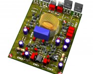
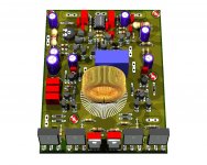
also i have made 2 pcb and both behave the same i have triple checked them for short and other issues. the idea of parallel the fets i borrowed it from here http://www.diyaudio.com/forums/class-d/184954-gzpa-class-d-4000w-irfp264.html here is the pcb
also i have made 2 pcb and both behave the same i have triple checked them for short and other issues. the idea of parallel the fets i borrowed it from here http://www.diyaudio.com/forums/class-d/184954-gzpa-class-d-4000w-irfp264.html here is the pcb
Attachments
thanks freda . will remove D7&D16 also Replace Q5&Q23 Q3,Q21,Q22,Q4 with BC639.
also i have made 2 pcb and both behave the same i have triple checked them for short and other issues. the idea of parallel the fets i borrowed it from here http://www.diyaudio.com/forums/class-d/184954-gzpa-class-d-4000w-irfp264.html here is the pcb
Hi,
The layout is not an optimal one for class-D. You considered a power plane but it is not the only one issue to give attention. One knows that discrete UCD circuit generates lower EMI if the correct layout topology followed. Just remove two of the output mosfets from each rail and leave the two of which are close to the center of the board. The 47pf's in the input pair should be replaced with 1n to 4.7n. If i were you, i would not try to do this one before testing your capability with an already made circuit. There are several examples in the forum with toner transfer files and correct component values. I hope you have a scope to see and record what is happening in the cricuit when you applied power. Try to work with +/-12V before +/-60V. And please put bulk caps (+one or several 100nf) from positive and negative PS rail to GND.
thanks freda. this schema has been working . but with irf540 +/-38vlts or either irf640 even irfp250 +/-55vlts but single not paralled and has been o.k now it is when i tried to get more that's when all my problems started i would love to do the above projects but i'm limited to smd components. with single outputs this circuit was working o.k
Hi
I'm fairly new at constructing anything on a breadboard but unfortunately my college decided to give me a project to build a fully discrete class d amplifier. I am considering building off the schematic posted in the first page (Phillips) just to know what exactly I'm up against. From there, try to construct my own class d amp with the given specific requirements.
Do you guys have any good advice for me because I really feel like my school just threw me in a fire and told me to dance ): ..
So far, for my own, I've made a triangle waveform generator using only discrete parts lol (http://dl.dropbox.com/u/14329675/trianglewaveform.PNG). So far I've studied that a class D has some parts which are the triangle waveform generator , the comparator to compare the waveform with the audio signal, the actual output stage and then a filter to change it back to an analog type waveform.
Anyway I don't want to write my life story but any advice would be appreciated!
Thanks!
Place a diffrentrial resistor in place of R9....it sets freq and dead time u need to set that for every mosfet if u change......i had posted a new thread after finishing with this thing....take a look at it..u can see I had cut a resistor below...i placed a potentiometer instead....but I can say its simple and awesome......with higher voltage....it is better than Ir2110
Place a diffrentrial resistor in place of R9....it sets freq and dead time u need to set that for every mosfet if u change......i had posted a new thread after finishing with this thing....take a look at it..u can see I had cut a resistor below...i placed a potentiometer instead....but I can say its simple and awesome......with higher voltage....it is better than Ir2110
btw did you mean r9 which is 220ohms in the below schema?
Attachments
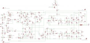
Sorry stewin.....its not that resistor I was talking about....i thought this design must be the original one which philips used....in this design you can se there is a differential resistor R36...it sets dead time and frequency....but when response is clear there is still some prob...output is never the same...when I got sine wave the output freq was more than 1khz... But response was good....btw did you mean r9 which is 220ohms in the below schema?
Philips Other UCD application
I see a lot of comments regarding the discreet version of a uCD amplifier. Y'all should check out the VAMP600 amplifier that used an integrated power comparator and power stage.
This amplifier works as-is, is stable, and remarkable in its presentation.
I have gerber files, BOM's etc. if anyone is interested. What's too bad is the Silicon is long since discontinued. Probably available in distribution though.
- Status
- This old topic is closed. If you want to reopen this topic, contact a moderator using the "Report Post" button.
- Home
- Amplifiers
- Class D
- Philips UCD application note