Hi there!
I decided to mod my T-amp following the steath mod as pictured here. Only problem was, when I modded the amp I accidently removed L3 from the board. I managed to keep the tiny surface mount component, and solder it back on as best I could (it was tricky!)
The other mistake I may of made was instead of bridging C3 and C4 I removed them from the board and bridged them on the PCB, again this was pretty tricky work and looking back I realised maybe what was suggested was that I keep the surface mount caps on the board and simply solder across to short them.
The input caps I am using are basic caps available from Jaycar electronics (see here
- are they ok? The idea was I would at least get the mod to work, then maybe experiment with better caps.
The only thing I did which was different from the stealth mod was bypass the pot completely as I am using a preamp. I did this by connecting the input caps directly to the RCA jacks that I am using.
ANYWAY - I hook it all up with new speaker terminals, power switch and case, and when I turn it on all I get is a hum, both channels. Power supply is connected the right way around.
I check the C3 and C4 bypasses, and carefully resolder C3 - it perhaps wasnt bridging the PCB pads properly. I now get no hum, but no amplified signal either.
I then decide to reinstate the wiring for the Pot, thinking that my bypass may be the reason why it isnt working, still no joy.
I am not sure what I have done wrong! I am thinking I may of somehow fried the T-amp, and I may need to get a new one but maybe not?
Any suggestions? If I have to buy a new T-amp, maybe I am better off getting a charlize amp and putting it in the case I already have.
Thanks for reading my first post here!
I decided to mod my T-amp following the steath mod as pictured here. Only problem was, when I modded the amp I accidently removed L3 from the board. I managed to keep the tiny surface mount component, and solder it back on as best I could (it was tricky!)
The other mistake I may of made was instead of bridging C3 and C4 I removed them from the board and bridged them on the PCB, again this was pretty tricky work and looking back I realised maybe what was suggested was that I keep the surface mount caps on the board and simply solder across to short them.
The input caps I am using are basic caps available from Jaycar electronics (see here
- are they ok? The idea was I would at least get the mod to work, then maybe experiment with better caps.
The only thing I did which was different from the stealth mod was bypass the pot completely as I am using a preamp. I did this by connecting the input caps directly to the RCA jacks that I am using.
ANYWAY - I hook it all up with new speaker terminals, power switch and case, and when I turn it on all I get is a hum, both channels. Power supply is connected the right way around.
I check the C3 and C4 bypasses, and carefully resolder C3 - it perhaps wasnt bridging the PCB pads properly. I now get no hum, but no amplified signal either.
I then decide to reinstate the wiring for the Pot, thinking that my bypass may be the reason why it isnt working, still no joy.
I am not sure what I have done wrong! I am thinking I may of somehow fried the T-amp, and I may need to get a new one
but maybe not?Any suggestions? If I have to buy a new T-amp, maybe I am better off getting a charlize amp and putting it in the case I already have.
Thanks for reading my first post here!
kaban said:
Any suggestions? If I have to buy a new T-amp, maybe I am better off getting a charlize amp and putting it in the case I already have.
Thanks for reading my first post here!
I'm no EE but I think you need a bridge to ground on your signal wires. Did you remove R01/02?
From what I've been told the resistors to ground need to be in front of the new capacitors so remove R01/02 and put in a 50K bridge on each signal wire before the caps (not after them).
(The pot usually creates the bridge on the stealth mod)
Again, I'm no expert but I have done a few of these babies and I think this will work.
Fingers crossed!
Lee
Hello Kaban, sorry to hear that you are haveing problems with your T Amp (lots of us have been there!).
Don't give up on it just yet, you still have a couple more opions. Without haveing to replace any of the tricky surface mounts you have already removed, you can try the following:
The first route is to remove L1 and L2 (I think you already had trouble with L2?). Then connect as per the diagram below with the new 47k resistors as shown,( as mentioned by Lee), if you intend to remove the Pot.
If this fails you can still try the Classic Mod shown here even with R01, R02, L1, L2, C3 and C4 removed!
Are these Amps a blessing or a curse? (yes they are GREAT when it all works!)
PS make sure you have a good grd from the phonos to the board and that your speaker terminals are not makeing contact with the case (if metal?). Good Luck.....
Attachments
Thanks!
I will give those suggestions a try and report back to you how I went.
Thanks so much for your help! I really love my t-amp and I was quite depressed about possibly damaging it. I am usually pretty good with electronics so having this happen after taking so much care was a bit sad!
Like I said in my first post, if I cant get it to go, I may order another one (or two!) or try a different t-amp kit.
It's fried
I tried what you suggested, but I think I have fried it. I think perhaps a careless solder join shorted out some part of it, at one stage it gave a puff of smoke. I can't believe it because I did work really carefully. I knocked the L1 surface mount and then tried to fix it, so I am thinking this is where I went wrong. Anyway, now it is no longer working in any capacity, so I have ordered a new T-amp and will try again!
I am totally mad, but hey, it's all a learning experience! Next time I will be more gentle with the surface mounts and really take my time.
When you bridge the caps on the board, should you leave them on and solder across the top to short them, or take them out completly? I think that is where I made my mistake.
sorry for the thread jack.
the left channel of my t-amp is dead. the right channel is working fine. does this mean that the chip is fried?
what i have done earlier was replace C10 with a better cap. parallel the 2 input rca of the 2 t-amps to eliminate the use of Y-splitter (for bi-amping). then hooked the amps back and noticed that the left tweeter wasn't working. both channels of the other amp are working which was hooked to the LF.
is there any chance i can resurrect the left channel?
hi kaban,
i have noticed that L1 came off the board probably when i brushed clean the pcb. found L1 but was not successful in soldering it back. i'm hoping that when L1 is back, the amp would work. my other alternative is to modify using audio1st mod 2. but this amp only power the tweeters. does auricap makes a good improvement on the tweeter or this is not necessary for this application?
i have noticed that L1 came off the board probably when i brushed clean the pcb. found L1 but was not successful in soldering it back. i'm hoping that when L1 is back, the amp would work. my other alternative is to modify using audio1st mod 2. but this amp only power the tweeters. does auricap makes a good improvement on the tweeter or this is not necessary for this application?
weng said:hi kaban,
i have noticed that L1 came off the board probably when i brushed clean the pcb. found L1 but was not successful in soldering it back. i'm hoping that when L1 is back, the amp would work. my other alternative is to modify using audio1st mod 2. but this amp only power the tweeters. does auricap makes a good improvement on the tweeter or this is not necessary for this application?
Hi Weng, don't bother altering the input if it's to be used for a tweeter. The only reason to 'stealth' a board is to cure the Bass roll-off, the highs are not an issue.
Lee
weng said:hi lee,
i also noticed that one side of L1 has a faded metal point. i will bring this to a cellphone technician for the installation. is there any replacement inductor available in case if L1 can't be soldered?
thanks
Thats the one thing that's never been measured, it would be interesting to find out the value of the input inductors.
Whether or not you need the input filter is questionable anyway!
I've done the classic modification and I thought it sounded better....slightly! and this bypasses the filter completely.
kaban said:
If I have to buy a new T-amp, maybe I am better off getting a charlize amp and putting it in the case I already have.
Yes. The Charlize is a better amp for not much more money. It's a very good amp. I have both, and very much prefer the Charlize.
Cheers
Bjørn
Hi weng, Lee is right about the filter part of the cct not affecting the sound noticeably. So you could just bridge L1 for now..weng said:hi kaban,
i have noticed that L1 came off the board probably when i brushed clean the pcb. found L1 but was not successful in soldering it back. i'm hoping that when L1 is back, the amp would work. my other alternative is to modify using audio1st mod 2. but this amp only power the tweeters. does auricap makes a good improvement on the tweeter or this is not necessary for this application?
Hi Weng, I don't think you will notice any difference in sound if you bridge L1, ( could even sound better). At least you will know if that is all that is wrong with that channel. You could then either remove the bridge and find a suitable replacement inductor, or bridge the other three... As for Caps, always use the best you can afford.
Barry...
Barry...
Re: Re: Fried t-amp?
Yes - and so I have done both! I bought another t-amp and a charlize amp with the handwound inductors! I am not bothering with any mod to the t-amp for now, I will wait and put the charlize in the case intended for my modded t-amp. By all reports the charlize is a slightly more powerful amp than the t-amp, and I will be interested in A/B-ing both of them as a test.
icebear said:
Yes. The Charlize is a better amp for not much more money. It's a very good amp. I have both, and very much prefer the Charlize.
Cheers
Bjørn
Yes - and so I have done both! I bought another t-amp and a charlize amp with the handwound inductors! I am not bothering with any mod to the t-amp for now, I will wait and put the charlize in the case intended for my modded t-amp. By all reports the charlize is a slightly more powerful amp than the t-amp, and I will be interested in A/B-ing both of them as a test.
Charlize - SI Questions
Nice Idea. I am considering doing the same with an Amp6 and a SI.
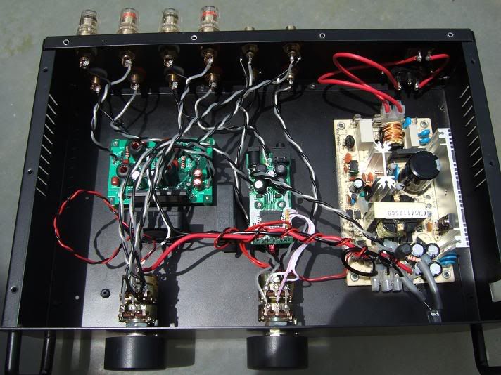
It appears that you have a switch mounted to the rear of you volume controls for each amp. Is that so?
What is the switch for, power, mute, etc.?
Do you use an external crossover that is feed to the Charlize-SI or do you use the X-over in the speakers?
It looks like you have a Switching PS. What is its rating and manufacturer?
How do the amps do with heat dissapation as currently configured?
TIA
Nice Idea. I am considering doing the same with an Amp6 and a SI.
It appears that you have a switch mounted to the rear of you volume controls for each amp. Is that so?
What is the switch for, power, mute, etc.?
Do you use an external crossover that is feed to the Charlize-SI or do you use the X-over in the speakers?
It looks like you have a Switching PS. What is its rating and manufacturer?
How do the amps do with heat dissapation as currently configured?
TIA
hi davet,
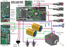
i am using an old ALPS 50K ohm pot with power switch at the back. in the case of the charlize this is where i put the soft-start resistor while with the SI is just a straight swap from the stock pot.
i only hook the charlize to the LF binding post and the SI to the HF binding post. dunno if this method still uses the x-over of the bookshelf speaker.
it is a 12V/5.2A smps made by a local electronic company here in the philippines. it powers the 2 t-amps. i have set it to 13.2V so the current should be below the rated 5.2A by now.
this is there website
Alexan Philippines
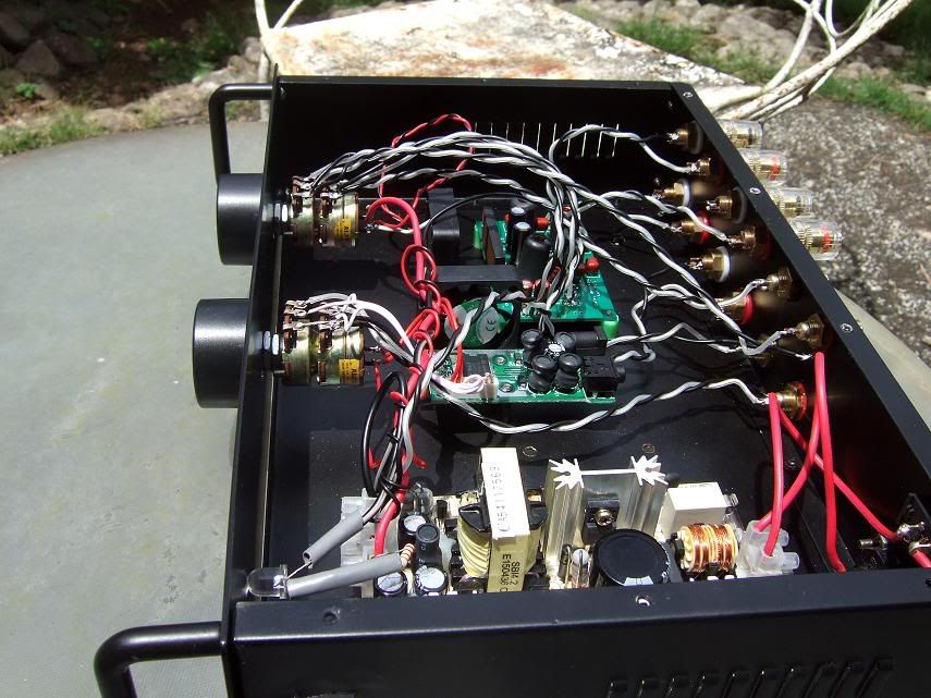
regarding heat dissipation, i have installed a small fan in front of each chip. it is difficult to see from top but this is the black thin thing at the back of the charlize chip and the other one is facing to the right to cool the SI chip.
here's another view of the amp with the SI fan visible.
i am using an old ALPS 50K ohm pot with power switch at the back. in the case of the charlize this is where i put the soft-start resistor while with the SI is just a straight swap from the stock pot.
i only hook the charlize to the LF binding post and the SI to the HF binding post. dunno if this method still uses the x-over of the bookshelf speaker.
it is a 12V/5.2A smps made by a local electronic company here in the philippines. it powers the 2 t-amps. i have set it to 13.2V so the current should be below the rated 5.2A by now.
this is there website
Alexan Philippines
regarding heat dissipation, i have installed a small fan in front of each chip. it is difficult to see from top but this is the black thin thing at the back of the charlize chip and the other one is facing to the right to cool the SI chip.
here's another view of the amp with the SI fan visible.
Neat Work
Apologies for highjacking this thread.
The use of the fans is a novel approach. I have a slew of small fans leftover from computer upgrades. This is something to be considered; especially if using a switching PS with the extra amperage.
It appears you have four RCA jacks. Do you use a Y-splitter from the source for input to the Charlize - SI?
One last question - How does the Charlize - SI sound?
- Status
- This old topic is closed. If you want to reopen this topic, contact a moderator using the "Report Post" button.
- Home
- Amplifiers
- Class D
- Fried t-amp?