Hey all...got myself a ZAPPULSE V2.1 and having a bit of problems with the power supply..
Got a 500VA dual secondary 40V transformer... 40V-0V on one pair and 40V-0V on another. I have two 35A rectifiers and four 10,000uF 63V Caps.
Having a bit of problems here - hooking up the way LC audio advises blows the fuse...
I did have luck pairing the two 40V to each AC input and taking their respective 0V as ground on each amp module....this way I got 56VDC off caps.
Connecting the 0V and 40V on AC input only gets me +/- 28V at each output....
Is there an issue with the way I am planning the Power Supply??
Got a pic below...
Attachments
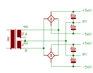
The schematic seems correct, though you may have encountered problems from not linking the two grounds (0V wires) together at the supply. The picture you attached may seem a bit confusing, you might want to take a look at Rod Elliot's supply design to clarify things a bit:

Note: The components on the left are not necessary unless you encounter ground loop problems.
Note: The components on the left are not necessary unless you encounter ground loop problems.
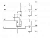
That first schematic is totally INCORRECT. The two secondaries should join together in the middle to form the ground connection.
The second schematic from ESP is correct and you should try to use that one. The centre-tap can be made by connecting the two 'inner' wires together like so:
0-40 0-40
.....|.|
connect these two
The second schematic from ESP is correct and you should try to use that one. The centre-tap can be made by connecting the two 'inner' wires together like so:
0-40 0-40
.....|.|
connect these two
Isn't there a PS schematic or design where I do not "make" the centertap by connecting the 40V and 0V?
I seem to think there is a design where the two secondaries feed two completely separate circuits (rectifier and cap bank)...just like two separate trannies...
And why do I get only +/- 28VDC out of the cap bank after connecting the 0V & 40V to the rectifier? I would expect +/- 28VDC output with 20VAC input, not 40VAC...
I have made quite a few PS for Gainclones, UCD180, etc., but this has me stumped...
The Torroid is from another amp...
Don't know if it makes a difference, but the tranny secondaries are listed as 40V 0V (0V) 40V....those parenthesis mean something here??
You mean like this:
Image taken from here: http://www.zero-distortion.com/techno/powersupply/powersi_05.htm
An externally hosted image should be here but it was not working when we last tested it.
Image taken from here: http://www.zero-distortion.com/techno/powersupply/powersi_05.htm
john, if you blew a fuse wiring up the supply as shown in the schematic in my post then you have a short somewhere or some component is bad or you used the wrong kind of fuse. You said you've made these kind of supplies before so I'm thinking you may have a bad bridge rectifier. Check each of the diodes with your multimeter.
With the way you're trying it ... seems like a poor blend of ideas.
It looks like you're trying to achieve some sort of phase cancellation... using a blend of the type of supply BWRX linked to with the one that PM650 linked to. You need to appreciate the differences between the two. One is of the fully isolated variety using the extra bridge rectifier, one per secondary, the other utilizes a typical center tap configuration. You can't have a mix of the two.
What you could do is expand on the ideas and use two more bridge rectifiers to achieve what I think you're after.
It's a little scary that you're using the term "luck" when it comes to a power supply like this. Might I recommend you test your idea on a free simulator like LTspice, before you cost yourself a set of blown up in your face caps or something?
Hope that's some help.
Well, I tried once again (without soft start) tried to connect the 40V and 0V to get a centertap as detailed in PM650's schematic. Blew a 6.3 amp slo blo fuse.
Whether I connect the secondaries before rectifier (as in PM650 schematic) or connect the DC + and DC - after the rectifier to get zero line (as in BWRX's schematic) I still end up blowing a 6.3A fuse.
I also measured all voltages off the secondaries. Confirmed both 40VAC to each 0V
The wires exit the bottom of the torroid in this fashion:
Blue (40V) Black (0V) Black (0V) Blue (40V)
Any other ideas?
By the way, this trannie came out f a KL-2400 Receiver that was trashed for parts...
I traced the two black 0V secondaries on the receiver amp board and the two black 0V tied together at the 4 pin connector - leads me to beleive that they together are the centertap.
I continues tracing the two 0V and the connected to the + and - of the power caps which is the zero line.
I think I now have it figured out...
OK, if it is a center tapped transformer then it won't work if you wire it up like the schematic in my other post.
Try going simple and wire it up like this circuit in this link that uses one bridge rectifier.
http://www.zero-distortion.com/techno/powersupply/powersi_04.htm
Also, have you checked all the diodes to make sure that they are not damaged?
Try going simple and wire it up like this circuit in this link that uses one bridge rectifier.
http://www.zero-distortion.com/techno/powersupply/powersi_04.htm
Also, have you checked all the diodes to make sure that they are not damaged?
BWRX --> I am troubleshooting before the rectifier - in other words, without the rectifier and Caps connected, the hot fuse blows when I connect the 40V to 0V to create the centertap.
ie, fuse blows when connected like this --> 40V (0V40V) 0V
The fuse does not blow when I connect the two 0V leads. I measure the two Blue 40VAC connections and I get 80VAC.
This is supposedly a Dual Secondary Tansformer. 40V 0V (0V) 40V.
Does anyone know if the parenthesis around the 0V means anything? This is the only "difference " I see from other dual secondary winding illustrations.
I fully understand this is really NOT supposed to work.
Ok then. From what you've just said you have a center tapped transformer. That must be what the parentheses around the second 0V means. The fuse blows when you connect the 40V to 0V because you're shorting out that winding. You can only do that when the secondaries are isolated from one another.
Try wiring it up like the schematic in my previous post and it should work. Or use the schematic BV posted if you need two sets of rails.
Try wiring it up like the schematic in my previous post and it should work. Or use the schematic BV posted if you need two sets of rails.
- Status
- This old topic is closed. If you want to reopen this topic, contact a moderator using the "Report Post" button.
- Home
- Amplifiers
- Class D
- Dual Secondary Tranny PS Issue