I have been building on my first class-d circuit for some time, and have had really good help by reading the pages here on DIYAudio.com ")
I started building the amp on a breadboard, and eventually it worked fine. Only problem was a kind of white noise, which was always present.
I thought that a real PCB would cure that, and it almost have, but it is still there to some extent!
Also when playing at very low levels the bass notes have a sound like clipping or metallic (a bit hard to explain in words)! Maybe it’s just the noise that is "modilated" in tune to the music
Also it is very sensitive to touch; If I place a finger on the driver IC (HIP4080), when it is not playing, the noise almost disappears, but placing a finger on one of the caps that controls the PWM freq, does the complete opposite.
I have done some measuring with a scope (Se my homepage ) and nothing really sheds any light on the problem!
I’m pretty sure that the problem is to be found around the PWM oscillator.
Could also be a fundamental grounding problem (Using a ground plane split into two to kind of separate analog from digital).
I'm using a virtual ground for some of the circuit, but as can be seen on my homepage, the "noise" on this ground is not at all alarming 50 mV pp)
Have tried to use NE5532 instead of TL072, but the integrator in the PWM ran pretty hot, and it was difficult to adjust freq. down to below 300 kHz.
The amp is running on a small 16 V DC PSU (until I know it is working properly ).
The amp is intended for a subwoofer, and hope to get it to deliver more than 300 W …. Eventually
The pots for adjusting the dead time is set to 220 k for maximum dead time.
Anyone who has any ideas??
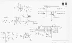
(Se attached diagram)
(Se picture of amp on hompage as well)
I started building the amp on a breadboard, and eventually it worked fine. Only problem was a kind of white noise, which was always present.
I thought that a real PCB would cure that, and it almost have, but it is still there to some extent!
Also when playing at very low levels the bass notes have a sound like clipping or metallic (a bit hard to explain in words)! Maybe it’s just the noise that is "modilated" in tune to the music
Also it is very sensitive to touch; If I place a finger on the driver IC (HIP4080), when it is not playing, the noise almost disappears, but placing a finger on one of the caps that controls the PWM freq, does the complete opposite.
I have done some measuring with a scope (Se my homepage ) and nothing really sheds any light on the problem!
I’m pretty sure that the problem is to be found around the PWM oscillator.
Could also be a fundamental grounding problem (Using a ground plane split into two to kind of separate analog from digital).
I'm using a virtual ground for some of the circuit, but as can be seen on my homepage, the "noise" on this ground is not at all alarming 50 mV pp)
Have tried to use NE5532 instead of TL072, but the integrator in the PWM ran pretty hot, and it was difficult to adjust freq. down to below 300 kHz.
The amp is running on a small 16 V DC PSU (until I know it is working properly
).The amp is intended for a subwoofer, and hope to get it to deliver more than 300 W …. Eventually
The pots for adjusting the dead time is set to 220 k for maximum dead time.
Anyone who has any ideas??
(Se attached diagram)
(Se picture of amp on hompage as well)
Attachments
Almost 100 reads and no replays from any of the gurus .... well no response at all!!
Well, I have played around with a few components, ending up with changing the loop resistor around the PWM stage, back to 47k, changing C12 to 1nF and C15 to 680 pF, and pacing a 4p7 ceramic between pin 5 a d 6 on the HIP (slowing the internal comparator down a little). This has almot cured the problem. The brake came form using the 4p7 ceramic on the comperator.
(The switching freq is now around 225 kHz, and the sound is good, though there is still a bit of noise when no music i palying)
Well I read in a thread somewhere that these noise problems maybe seems to be more or less inherent to class-d (switching noise that couples to the rest of the amp through loops etc.)
Then the only real cure is even more carefull design of PCB and use of SMD components.
What about snubbers on all the Mosfets ..... will that help eny, in this respect?
What about freewheeling diods on all the Mosfets?
How do you determin whether these are necessary, and how do you determine the rating in A needed?
Baldin
Sensible Audio
Class D is not trivial as you may have noticed, not many people in the whole world are experts.
Isn't 300 kHz way over the IC's specs? have you read the article in Elektor (rather recently) where they investigated a class D amp made of a HIP IC? The conclusion was: Not very very good PWM IC for audio.
Isn't 300 kHz way over the IC's specs? have you read the article in Elektor (rather recently) where they investigated a class D amp made of a HIP IC? The conclusion was: Not very very good PWM IC for audio.
I'ts running below 250 kHz, which should be no problem for the IC.
No I haven't seen that article .... do you know which exact issue .... then I could download it from their homepage (3.80£)
I'd like to see why this should be such a bad IC for a class-d amp!
.... but I know it's reputation is maybe not the best, though I chose it because of the easy way to adjust deadtime, it's drive capacity, the build in comparator etc.
Mads
Sensible Audio
Thanks for your answers so far
Have tried out a few things:
Mounting diodes parallel with the gate resistors (1N4148) have helped a bit with the noise, and defenetly with the heat disipation, especially in the LM7812 regulator the the driver IC!
Adjusting the resistors for delay on pin 8 and 9 from 220k to 115k has reduced the noise to a mere humm (not white anymore) which is affected bu tuching the ibput components (more of the same noise)
A 470 uF decoupling close to the Vdd/Vcc of the HIP is helped too.
More decoupling on the virtual ground does not seem to help any. But then again, I havent tried omitting the buffer as you suggested Brian ..... a bit too dificult on the current PCB
All in all, noise is down to almost nothing. Next step will be to raise the supply voltage and se what happens
Have read on Tripath's hompage that the gate resistors for the output FETs should be of at least 1W!!!! Is that really so?
I'm wondering whether the LM7812 used for the driver is actually good enough for this task. What are others experience in this matter??
The use of a 470 uF on the output side of the regulator seems excessive, and will render it's regulating ability somewhat useless! But is it any good with loads in the 250 kHz range??
What are you using for driver PSU??
What about the external freewheeling diodes over the MosFets, are these necessary, and how do you calculate the needed rating??
What about snoopers on the MosFets do you all use these??
At the moment I'm not using either.
Thinking about changing the PSU to the driver stage to a switched PSU (small swiched regulator from Linear Tech.) ..... any comments on that??
What about snoopers on the MosFets do you all use these??
At the moment I'm not using either.
Thinking about changing the PSU to the driver stage to a switched PSU (small swiched regulator from Linear Tech.) ..... any comments on that??
Tried out the amp vith a higher voltage on the H-Bridge.
No problems with noise ..... seems to be a thing of the past with the described modifications
But the output coil is getting dangerosly hot!!!!!
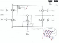
Just by switching! Signal/music is coming through no problem, but the switching frequency has changed to 140 Hz (se scope shot).
The two coils for the diferential filter is wound around the same coil former (a former I had laying around .... think it must have been used in an SMPS as it had two windings, 2:1) and has 2 times 18 windings giving 2 times 30 uH. (this should mean that it's permability is rather low, and I gues therefore well suited for this application).
The colils are connected so that the current through these runs "the same way" building on the same magnetic field.
...... is this a no go???
No problems with noise ..... seems to be a thing of the past with the described modifications
But the output coil is getting dangerosly hot!!!!!
Just by switching! Signal/music is coming through no problem, but the switching frequency has changed to 140 Hz (se scope shot).
The two coils for the diferential filter is wound around the same coil former (a former I had laying around .... think it must have been used in an SMPS as it had two windings, 2:1) and has 2 times 18 windings giving 2 times 30 uH. (this should mean that it's permability is rather low, and I gues therefore well suited for this application).
The colils are connected so that the current through these runs "the same way" building on the same magnetic field.
...... is this a no go???
Hmmmm, after reading a bit and thinking a bit, I guess it's not such a surprise, as it must be caused by Hysteresis losses.
As far as I can find out the loss can be described by
Physteresis = Kn x f x B^n ;
where Kh is a factor that is determined by the core material, as is the factor n, which for iron should be around 1.6
f is the frequency and B is the flux density
B = Ø / Ae ;
where Ø is he total flux and Ae is the effective area of the core
Ø = (L x I)/N
where L is the inductance, I is the current and N is the number of turns
It can be seen that Ø is proportional to the coil voltage as the current I must be proportional to the voltage in "idel" mode (without music)
As the voltage to the H bridge was changed from 17 V to 56 V, the loss was increased over 175 times (the frequency droped to about half ... don't know why, and the loss is also proportional to f ... otherwise it would have been 320 times). So if there was any loss to start with it now became not so neglectable and the core got hot.
So I guess the core is just not suited for this task (f and V).
.... at least thats my explanation so far .... any comments?
I have made measurements on the coil, by making 8 turns with a wire round it and measureing with a scope. At 17 V it seems to work just fine, and is connected correctly. As far as I can see, the ICEPower modules are also using one core ring for both coils .... guess it's ok if you use the right core material
Anyone know a good online store where thay have a good range of suitable ring cores?
Thanks Eva
Well I was thinking on lowering the corner freq anyway. Think that in this design, which is intended for a sub-woofer, lowering the corner freq would gain more that it would hurt
But I think I will try another core anyway.
From what I read in this forum, and from what others uses commercially, I can't really decide what is best; toroids or air gaped cores. ..... what will give the best result wrt. loss and distortion??
Can't really find a good source for suitable toroids, but RS Components, have RM 12 and RM 14 cores from Epcos with air gap and an Al of 250 nH ...... Guess this would be quite suitable .. but I'm not sure that the RM 14 will be big enough for a 400 W amp!
Guess I should read some more about coils
Follow up on a very old thread
Just a follow up on a very old thread.
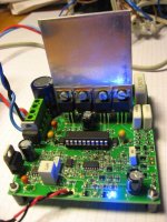
My full bridge HIP4080A SODA is coming along quite well.
No more noise
It's running on +54V at the moment. Next step is putting a 500VA 50VAC + 22000 uF Rifa on and put it to good use in my Peerless XLS sub
Still som improvements could be done, but I think I'll move forward on another project instead!
More infor on my homepage:
http://home20.inet.tele.dk/audio/HIP4080_SODA_Class-D/hip4080_soda_Prototype2.htm
Just a follow up on a very old thread.
My full bridge HIP4080A SODA is coming along quite well.
No more noise
It's running on +54V at the moment. Next step is putting a 500VA 50VAC + 22000 uF Rifa on and put it to good use in my Peerless XLS sub
Still som improvements could be done, but I think I'll move forward on another project instead!
More infor on my homepage:
http://home20.inet.tele.dk/audio/HIP4080_SODA_Class-D/hip4080_soda_Prototype2.htm
Attachments
- Status
- This old topic is closed. If you want to reopen this topic, contact a moderator using the "Report Post" button.
- Home
- Amplifiers
- Class D
- Noise problems in non discrete class-d amp