I have diodes on the fets gate resistors.
Thx for the time. I´ll wire back the TL as it was when i started, but wire one output as common emmitter and one as common collector as u said.
For deadtime a properly working IR2010 should prevent the fets for beeing turned on as the same time.
Thx for the time. I´ll wire back the TL as it was when i started, but wire one output as common emmitter and one as common collector as u said.
For deadtime a properly working IR2010 should prevent the fets for beeing turned on as the same time.
Pafi, you are right, but there is no reliable way to control dead time.
Tekko: Any overlapping must be avoided, you are going to need 100ns or 200ns of dead time to compensate for any overlap and for gate discharge times and to allow for resonant operation at low speaker currents (highly desirable). You may obtain that by inserting RCD networks between the TL494 and the IR2010.
Tekko: Any overlapping must be avoided, you are going to need 100ns or 200ns of dead time to compensate for any overlap and for gate discharge times and to allow for resonant operation at low speaker currents (highly desirable). You may obtain that by inserting RCD networks between the TL494 and the IR2010.
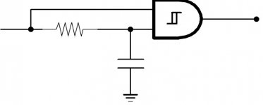
Yes Tekko, that seems like PWM. Concerning the RCD network, imagine a capacitor charged through a resistor and discharged through a diode. That produces a long time constant for half the edges and a short time constant for the other half.
Another good approach is the one show by Ouroboros.
Another good approach is the one show by Ouroboros.
I start to think about skipping tl494 (actually its KA7500B i have) alltogether and just make one of these: http://www.4qdtec.com/pwmmod.html
Now i am building a second prototype with improved wiring layout.
Could it be a good idea putting a small cap rated 0.1µF parallel with a 100pF cap between vcc and gnd legs on the IC´s , or would that cause worse ringning than without ?
What do you think about a on board 7815 15v voltage reulator to feed the IC´s ? I noticed yesterday that the 12v puter ps just gave 10.6v when driving the classd.
Build yourself a decent adjustable power supply, or modify the AT/ATX one that you have to suppress all unused outputs and add a potentiometer to allow adjustment of the remaining 12V output. Internal cross-regulation in any unmodified PC PSU will prevent drawing too much current from the 12V line without drawing it also from the 5V line.
Also, think a bit about filter resonance... You have to figure out yourself the kind of disaster that would arise if the switching frequency was set even just close to filter resonance.
Also, think a bit about filter resonance... You have to figure out yourself the kind of disaster that would arise if the switching frequency was set even just close to filter resonance.
Heres a lil scope capture video at pretty loud volume:
http://user.faktiskt.se/Tekko_Tubeamp/D-amp back from the dead/scope shots/D-Amp with music.AVI
http://user.faktiskt.se/Tekko_Tubeamp/D-amp back from the dead/scope shots/D-Amp with music.AVI
Try this:
1. Press the link. You'll get an "forbidden" message
2. Then in the address field of your browser, you edit the address by deleting both the filename and first directory, so that the the address is now pointing to the directory above.
Like this: (don't press the link .... it will not work)
http://user.faktiskt.se/Tekko_Tubeamp/D-amp back from the dead/
3. Press enter. Hopefully you'll have access to all directories and files")
1. Press the link. You'll get an "forbidden" message
2. Then in the address field of your browser, you edit the address by deleting both the filename and first directory, so that the the address is now pointing to the directory above.
Like this: (don't press the link .... it will not work)
http://user.faktiskt.se/Tekko_Tubeamp/D-amp back from the dead/
3. Press enter. Hopefully you'll have access to all directories and files
- Status
- This old topic is closed. If you want to reopen this topic, contact a moderator using the "Report Post" button.
- Home
- Amplifiers
- Class D
- level shifters and mosfet drivers