")
Yes indeed.
I have been beavering away at a closed loop digital design along the lines of that presented at the 37th AES International Conference by Bruno Putzeys and Toit Mouton: Hillerød, Denmark, 2009 August 28–30. This has involved a lot of pencil and paper calcs, Matlab design scripts, and a dedicated MSVC real time simulator program I wrote.
I have confirmed the performance results quoted in this paper, including the load resistance range for stability. (Quoted 2.6 to 35 ohms - I get a very similar result). In the real word, unfortunately, this is not adequate for a robust amplifier. The real component of speaker impedance can easily push the boundaries of this range, and speakers can and do become disconnected or suffer shorts. (Not all shorts will cause overload trip, as the amplifier may not be delivering power) See the Ken Kantor plots in stereophile magazine.
For robustness, I want a resistance range of 0.1 ohm to 500 ohms, since loading higher than this can be constrained by a permanent resistive load without wasting excessive power.
I could not obtain unconditional stability over this range, even with the addition of a Zobel damping network in the LC filter. There are two ways forward from this point:
a) Place the LC filter outside the loop, replace it with a fixed analog filter, using a high grade diff in diff out op-amp. I have verified that a design similar to that of the Putzeys/Mouton manages unconditional stability on all load values with this method, as would be expected. The price paid (amongst others) is that errors due to inductor non-linearities are not corrected, necessitating the use of bulky and expensive air cored inductors. Nevertheless, the corrective power of the control loop is really impressive! I have simulated bad unregulated PSU's, a slew of even and odd harmonics at -50dBFS, and white noise, all together,representing really sloppy power stages. The feedback cleans it all up.
b) Start again with a different concept, which is the route I have chosen. At this point I'd rather not say more, as aspects of the concept are quite novel, although the concept itself is old, and hails from the field of switching PSU design. There is still a closed loop around everything. I'm about halfway done now. The 'novel bit' works well, and the 'old concept' seems set to as well. The design is targetted at an Altera FPGA, not sure which one yet.
Obviously, there are still things that can go wrong, so I'll have to beaver on and see what emerges. This is not something one can knock up over a weekend with a soldering iron and some FETs. But boy is it rewarding when you look at a spectral result! Objectively it's probably all pointless because speaker linearity is orders worse, but there's nothing like an engineering design challenge. . .
Cheers
John
Last edited:
Great to hear from you.
Closed loop like the new TI chips, or another technology (I'm not a tech wiz)?
I have been looking for an open loop solution, but they are hard to find. The reason is, that this technology have been the only one I have heard, that can really pin out every detail in complex recordings. The reference for me is Tact (now Lyngdorf) Millenium, but also Panasonic SA-XR50 can do this. I also love my NXP8950th based amplifiers, but they do not have that detailed midrange, but the low range is really good, and much better than Panasonic SA-XR50.
The analogue PWM models from Lyngdorf have not impressed me as much as the equibit based Millenium
Last edited:
I have built several open loop digital amps and use two at home on a daily basis and have done for over 12 years. They are very similar performance to the TacT Millenium, which was the first high end open loop digital amp, around 140W/ ch and similar THD. My open loop amps sound really spectacular according to those with the 'golden ears'.
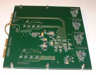
In 2009 I built a prototype of a no expense spared open loop amp that had THD of 0,02% and delivered 175W/ch. I laid out a board even, but one day I looked at it all and decided it was disproportionately complex, and the whole open loop concept went against the grain of sensible engineering, no matter how good it auditions. I didn't feel like taking it to fruition. so did no audio work at home for three years until I started my closed loop design last autumn. I wrote an article about my open loop amps - PM me if you want me to send it to you.
On paper, a well engineered closed loop design can achieve THD/N of around 120dB, as did the one in Bruno's article I mentioned. It's limited by the performance of the ADC used for feedback, an AD7760. This is 0,0001% , 100x better than a max effort open loop amp.
Cheers
John
- Status
- This old topic is closed. If you want to reopen this topic, contact a moderator using the "Report Post" button.
- Home
- Amplifiers
- Class D
- Anyone interested in a digital amplifier project?