Reply
1.This is't advertisement, Only for show.
2. "Topology different from others" isn't a new principle or theory presented. It means I have something original, for example circuit diagram and some devices.
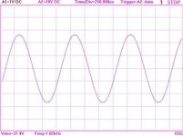
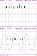
3. One feature of this class d is unipolar modulation using either positive or negative pulses but not both, similarly to DDX of Apogee or ZXCD1000 of Zxtex. The other is constant PWM frequency modulation with feedback.
4. The result is its output wave is fine then bipolar modulation.
1.This is't advertisement, Only for show.
2. "Topology different from others" isn't a new principle or theory presented. It means I have something original, for example circuit diagram and some devices.
3. One feature of this class d is unipolar modulation using either positive or negative pulses but not both, similarly to DDX of Apogee or ZXCD1000 of Zxtex. The other is constant PWM frequency modulation with feedback.
4. The result is its output wave is fine then bipolar modulation.
Attachments
3. One feature of this class d is unipolar modulation using either positive or negative pulses but not both, similarly to DDX of Apogee or ZXCD1000 of Zxtex. The other is constant PWM frequency modulation with feedback.
So it is actually class-BD, isn't it ?
Regards
Charles
Lars Clausen said:We are all curious to see the schematics, especially if there is any new and interesting solution.
However publishing a sch is a bit of a risk. Not so much because of the danger of somebody copying the design, and mass producing it. This is not a very high risk, because, believe me, the producers who are interested in Class D technology, they have it already.
The risk is more that people here will breadboard the schematic to try it out how it sounds. And with a DIY PCB or breadboard, you are bound to end up with a poor or useless result. So the product may get a bad reputation based on it's breadboard performance, even if it has great performance on the producer's 4 layer PCB.
So i would be understanding if dr Zhuang is reluctant to post his schematics. However a nice explanation about what makes his amp different than others, would be very interesting
How much is this in US$ ??
")
Divide RMB by about 8.5 for us$ Very inexpensive.

The output stage shown in that thread is not quite suitable for class BD:
http://www.diyaudio.com/forums/showthread.php?postid=890855#post890855
If you are latching one of the sides of the bridge to one supply rail as required, and using the other side to track the corresponding half of the output waveform, slew rate limitation issues and unacceptably high crossover distortion are likely to happen at high frequencies.
Note that one of the major flaws of the "two switches and an inductor" topology is that both voltage and current "slew rates" towards each rail are inversely proportional to the voltage difference between the output and that rail. That in turn means that the bandwidth is progressively reduced to 0 as the output gets closer to the rails. So if you latch one side of the bridge to one rail, you will have 0Hz bandwitdth in that side for some time until some voltage builds up when you try to unlatch it.
BTW: I have implemented something similar to B+D with symmetrical suplies. The load (inductor) was either actively forced to rest at ground or allowed to freewheel to the opposite rail when required. It wasn't high frequency PWM but a quasi-sine 2.4KW mains inverter doing PWM directly at 120hz, though.
Re: Reply
topology
1. <mathematics> The branch of mathematics dealing with
continuous transformations.
A very good book on the subject is "Introduction to Topology" whose author I forgot, but its cover is red. A most fascinating book I was asked to translate therefore I had to study it.
That said, topology is often misunderstood or misused. Using a H-bridge and modulating it in ternary - or tri-state - doesn't make it a new topology, imho.
By the same token, showing a sine isn't showing a topology either. Any dumb function generator can do that.
In brief, "where's the meat?"
drzhuang said:1.This is't advertisement, Only for show.
2. "Topology different from others" isn't a new principle or theory presented. It means I have something original, for example circuit diagram and some devices.
3. One feature of this class d is unipolar modulation using either positive or negative pulses but not both, similarly to DDX of Apogee or ZXCD1000 of Zxtex. The other is constant PWM frequency modulation with feedback.
4. The result is its output wave is fine then bipolar modulation.
topology
1. <mathematics> The branch of mathematics dealing with
continuous transformations.
A very good book on the subject is "Introduction to Topology" whose author I forgot, but its cover is red. A most fascinating book I was asked to translate therefore I had to study it.
That said, topology is often misunderstood or misused. Using a H-bridge and modulating it in ternary - or tri-state - doesn't make it a new topology, imho.
By the same token, showing a sine isn't showing a topology either. Any dumb function generator can do that.
In brief, "where's the meat?"
Originally posted by Eva
This is not BD type class modulation but rather one that is used in stepper motor drivers. Proper class BD is two AD class carriers displaced 180 degrees. This results in two problems:
-common mode noise if single supply bridge is used
-and inevitable influence from one power stage to the modulator and driver of another power stage since both power stages switch only several nanoseconds apart at small modulation index.
Best regards,
Jaka Racman
If you are latching one of the sides of the bridge to one supply rail as required, and using the other side to track the corresponding half of the output waveform, slew rate limitation issues and unacceptably high crossover distortion are likely to happen at high frequencies.
This is not BD type class modulation but rather one that is used in stepper motor drivers. Proper class BD is two AD class carriers displaced 180 degrees. This results in two problems:
-common mode noise if single supply bridge is used
-and inevitable influence from one power stage to the modulator and driver of another power stage since both power stages switch only several nanoseconds apart at small modulation index.
Best regards,
Jaka Racman
Oh, I understand. So the traditional phase-shifted full bridge (where both upper and lower switches are driven at the same time for 0V net output, and output ripple ranges from full common mode at 0V output to full differential mode at maximum output) would be called class BD in switching amplifier contexts.
Q: What is you product
A: Different from orthers
Q: Is it #$%@?
A: "500W CLASS D". IS it clear?
Q: What makes class Z unique ?
A: You can call my product anything at will
Q:
A: Demo
Q: @#$%&
A: I called it unipolar PWM refer to SMPS.
Summary: 500W Class-D Unipolar PWM
What else ?
A: Different from orthers
Q: Is it #$%@?
A: "500W CLASS D". IS it clear?
Q: What makes class Z unique ?
A: You can call my product anything at will
Q:
A: Demo
Q: @#$%&
A: I called it unipolar PWM refer to SMPS.
Summary: 500W Class-D Unipolar PWM
What else ?


Hello drzhuang.
I've been having a prod about on the basis of the information you have provided so far.
My first question would be about the output filter.
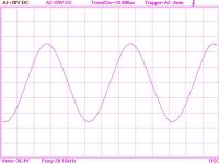
You suggest a 500W output power and your plots give an output of 37V RMS which implies a sort of 3 ohm load. For a 2ohm load you would need about 45V RMS.
Your filter comprises two 22uH inductors and two 470nF capacitors which are effectively in series. So the equivalent is 44uH and 235nF.
The cut off frequency would be 50KHz but the resonant impedance is about 13.5 ohms. This implies that your filter is going to be heavily overdamped.
I realise that loudspeakers are non ideal loads and there is an opportunity to 'tailor' the response for a particular load but, for a 2 ohm load your filter will assume a first order LR roll off at about 7KHz which might be too low.
There is a problem that arises from current slew rate limiting in the inductor depending upon its value and the available supply voltage. It will make the compensation networks 'interesting' as well.
You also add parallel damping to your filter with a 220nF|220R series combination which, effectively, achieves nothing. Perhaps 680nF with 15 ohms would be better.
At the moment I am slightly confused (I cannot deny I am a novice as well). I'll spend a bit of time looking at what you have given so far but obviously it will be helpful if you, or someone else, can provide further information.
Thanks
DNA
I've been having a prod about on the basis of the information you have provided so far.
My first question would be about the output filter.
You suggest a 500W output power and your plots give an output of 37V RMS which implies a sort of 3 ohm load. For a 2ohm load you would need about 45V RMS.
Your filter comprises two 22uH inductors and two 470nF capacitors which are effectively in series. So the equivalent is 44uH and 235nF.
The cut off frequency would be 50KHz but the resonant impedance is about 13.5 ohms. This implies that your filter is going to be heavily overdamped.
I realise that loudspeakers are non ideal loads and there is an opportunity to 'tailor' the response for a particular load but, for a 2 ohm load your filter will assume a first order LR roll off at about 7KHz which might be too low.
There is a problem that arises from current slew rate limiting in the inductor depending upon its value and the available supply voltage. It will make the compensation networks 'interesting' as well.
You also add parallel damping to your filter with a 220nF|220R series combination which, effectively, achieves nothing. Perhaps 680nF with 15 ohms would be better.
At the moment I am slightly confused (I cannot deny I am a novice as well). I'll spend a bit of time looking at what you have given so far but obviously it will be helpful if you, or someone else, can provide further information.
Thanks
DNA
When feedback is taken after the filter, interesting things happen. We can't just assume that he is doing it that way, but for example, now I'm listening to a stupid breadboard prototype (that was not intended to play audio at all but to drive motors!!) whose filter resonance is at 3600Hz (130uH and 16.4uF). However, I started to play with the compensation and now it plays almost flat up to 12Khz (within +1.5dB/-6dB, with or without load). It suffers strong slew rate limiting above 6Khz as it's a single rail 32V supply (with capacitively coupled 4 ohm load), though. Even funnier is the switching frequency range I'm employing: 28 to 54Khz (keeping constant inductor ripple down to 28Khz).
- Status
- This old topic is closed. If you want to reopen this topic, contact a moderator using the "Report Post" button.
- Home
- Amplifiers
- Class D
- 500w Class D