hello,
A new classD manufacturer: CL3 , a french society")
They use a full bridge technology. Gemincore sound very well.
Take a look at www.Cl3.FR
@++ Seb
A new classD manufacturer: CL3 , a french society
They use a full bridge technology. Gemincore sound very well.
Take a look at www.Cl3.FR
@++ Seb
I just looked at Ambruschi US application dated Feb 2004.
Complementary totem pole has been used in class AB amps, including MOSFET output stage, and in many bipolar driver stages driving mosfet.
The question is what is new in CL3 circuit? The fact Ambruschi learned about its minimum shoot-thru doesn't make it new, only new to him.
Complementay totem poles have been around in the 70's at least, in bipolar output stage. Now isn't that obvious that mosfets can also be used instead of bipolar?
Source follower?
If you think of this as just an impedance conversion then it looks to have some very real advantages. The drive can be simplified and optimized very nicely. The problems are exceeding the gate voltage when the output can’t track (shorted output) and the necessity of driving over the rail voltage to get full on at the rails. Also the fact that hi voltage “P” type device selection is very limited. These are the real stumbling blocks to this design. A transformer drive with a step up ratio would be an easy solution to some of the problems. This could also generate the oposite phase for bridge drive.
This could be the configuration of choice for lower power. Maybe up to 24 volts total? With proper design in a full bridge this could give well over 200 watts into 4 ohms. This would be enough for serious consideration I would think.
I will have to think about this a lot more.
Roger
Hi Folks,
I am currently working on this Grounded Source Follower topology for lower power versions upto 200W in Class-D complementary FETs...Easy drivability and low cost.....Whereas my high power versions use N-channel Mosfets only....
Have a look....
regards,
K a n w a r
I am currently working on this Grounded Source Follower topology for lower power versions upto 200W in Class-D complementary FETs...Easy drivability and low cost.....Whereas my high power versions use N-channel Mosfets only....
Have a look....
regards,
K a n w a r
Attachments
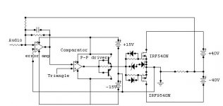
Sorry Kanwar, I should have looked closer, without zooming the loss of graphic quality showed the negative source as -5 instead of -15V. Nevermind.
Are you sure their patent isn't written in such a way as to include grounded source follower? Surely it must
I dont' think they stand a chance in hell of defending that patent and doubt they'd try. More likely it's one of those patents used to ensure their own usage of the circuit without any problems from competitors?
Would seem to be an interesting circuit to experiment with for low power output.
classd4sure said:
Are you sure they're patent isn't written in such a way as to include grounded source follower? Surely it must
I dont' think they stand a chance in hell of defending that patent and doubt they'd try. More likely it's one of those patents used to ensure their own usage of the circuit without any problems from competitors?
Would seem to be an interesting circuit to experiment with for low power output.
Yes, there patent is different they take the output from the sources of both switches, but mine is grounded simply Zero reference node....
If you see their AES convention paper..it states the method of switches operation...their output as well....but things are different here...
regards,
K a n w a r
AAaah I also missed your little patent circumvention trick by not zooming in.... assumed there'd be a filter there. Did you throw this together today? lol
Where is your filter anyway.
I love the trick, that's just too funny!
I confess I didn't spend much time with the AES paper, 30 seconds? Did not look up the patent either, will get to that shortly
Where is your filter anyway.
I love the trick, that's just too funny!
I confess I didn't spend much time with the AES paper, 30 seconds? Did not look up the patent either, will get to that shortly

- Status
- This old topic is closed. If you want to reopen this topic, contact a moderator using the "Report Post" button.
- Home
- Amplifiers
- Class D
- New classD amp: Gemincore of CL3