I saw almost people design the triangle wave is 4Vpp.
If the input signal near 2V , the square wave of comparator output will near 100% duty.
will it damage the output mosfet ??
How to decide the amplitude for triangle and limit of input signal??
Because i fair that if input signal near to triangle wave peak amplitude will damage the output mosfet.
So, I limit the input signal only has 70% of triangle wave peak amplitude.
And Let the Gain of amp become higher to amplifier the signal.
Did the think right??
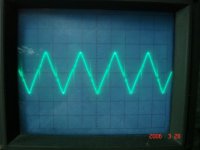
I probe the output wave , when output amplitude near +/-Rail to saturate.
The wave form has much high-frequency hormonic at high side and low side.
Dose anyone also has the situation??
If the input signal near 2V , the square wave of comparator output will near 100% duty.
will it damage the output mosfet ??
How to decide the amplitude for triangle and limit of input signal??
Because i fair that if input signal near to triangle wave peak amplitude will damage the output mosfet.
So, I limit the input signal only has 70% of triangle wave peak amplitude.
And Let the Gain of amp become higher to amplifier the signal.
Did the think right??
I probe the output wave , when output amplitude near +/-Rail to saturate.
The wave form has much high-frequency hormonic at high side and low side.
Dose anyone also has the situation??
Then i reconnect the mosfet to the pcb.
And add a dead time control befroe ir2110 HI and LO input.
Turn on the power , i saw the current disspation become more.
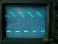
I probe the output of the mosfet ,,,
Its waveform has some problem.It get a ramp.
(If i remove the L out , the output waveform form looks good.
It is a sqaure waveform , and no other problem.)
Picture above here : T=5us/div V=20v/div
And add a dead time control befroe ir2110 HI and LO input.
Turn on the power , i saw the current disspation become more.
I probe the output of the mosfet ,,,
Its waveform has some problem.It get a ramp.
(If i remove the L out , the output waveform form looks good.
It is a sqaure waveform , and no other problem.)
Picture above here : T=5us/div V=20v/div
Attachments
When i turn on power after few second ,,,
I saw the resistor before mosfet's Drain pin starting burned.
( if i didn't add the dead time control , the resistor get bomb immediately)
1. Is that because the modulation frequency too slow ???
2. what is the correct waveform after RC-filter in feedback network ??
someone said the RC-filter freq must equare to modulation freq.
someone said the RC-filter freq must lower than the modulation freq.
I got confuse about it.
I don't know how to designe the RC-filter in feedback network.
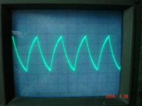
If i designe the LPF freq. = modulation freq.
The waveform looks like a square wave also ,but it get smooth at coner.
If i designe the LPF freq. = (modulation freq)*0.8 .
The waveform looks like a triangle wave.
Picture above here. T=5us V=20v/div
which way is right ???
I saw the resistor before mosfet's Drain pin starting burned.
( if i didn't add the dead time control , the resistor get bomb immediately)
1. Is that because the modulation frequency too slow ???
2. what is the correct waveform after RC-filter in feedback network ??
someone said the RC-filter freq must equare to modulation freq.
someone said the RC-filter freq must lower than the modulation freq.
I got confuse about it.
I don't know how to designe the RC-filter in feedback network.
If i designe the LPF freq. = modulation freq.
The waveform looks like a square wave also ,but it get smooth at coner.
If i designe the LPF freq. = (modulation freq)*0.8 .
The waveform looks like a triangle wave.
Picture above here. T=5us V=20v/div
which way is right ???
Attachments
I just has a ideal ...
1. Maybe it's because of my gate resistor too large 100ohm.
when i use 200Khz modulation freq , Rg=100ohm is OK .
I will try lower the gate resistor .
2. Maybe the bootstrape cap too small.
Now i use 1uF cap be the bootstrape cap.
But i don't have any ideal to know it's too large or small..
I also will try it tomorrow.
If anyone has any ideal ,,, please tell me your think ... thanks !!
if pic in post #3 representing good sqare shape then you suffering from low bootstrap capacitance, in other words speaking try bigger value like 10u or 22u, but use low-ESR cap or smd tantalum, 100ohm might be large and might not, depends, anyway it setting dead time and makes rising edge of gate signal to act slower. . .
Have a look at...
http://www.genomerics.org
The first two parts under "Class D Amplifiers" may give you some ideas about how to work out component values for pre-filter feedback.
Sorry, it's not the full story yet, Work In Progress (WIP), but hopefully it's of some use to you.
Cheers
DNA
http://www.genomerics.org
The first two parts under "Class D Amplifiers" may give you some ideas about how to work out component values for pre-filter feedback.
Sorry, it's not the full story yet, Work In Progress (WIP), but hopefully it's of some use to you.
Cheers
DNA
zkaiser said:if pic in post #3 representing good sqare shape then you suffering from low bootstrap capacitance, in other words speaking try bigger value like 10u or 22u, but use low-ESR cap or smd tantalum, 100ohm might be large and might not, depends, anyway it setting dead time and makes rising edge of gate signal to act slower. . .
I have try to increase the bootstrape cap to 5uF.
Because i only has 1uF tantalum in hand.
So , i parallel 5 to get 5uF. But it seems doesn't improve.
And i try to decrease the gate resistor to 33ohm , 22ohm and 10ohm.
Still do not work too well.
I will think about it more ,,,
Thanks All .....!!
titanchen68, hi !
I've been thinking something, and reason that yours amp doesn't work might be in level shifter for ir2110, and BTW how you supplying triangle generator and lt1016 there are no volt regs. on schematic ?
Use my drawings of voltage levels and proposed level shifter in try to solve out working issues in your amp.
Can you post latest pic of amp board and stuff ?
Best regards
Zeljko Kaiser
Attachments
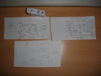
This is my final circuit ....
do i have to use the dead time control ??
because i feel it doesn't has any advantage for me.
I really feed the dead time circuit will break the square waveform of input of IR2110.
Thanks for your circuit ... really ....
It looks only the level shift is different from mine.
do you think my level not good or something else ???
Attachments
do you think my level not good or something else ???
yes you actually passing a way more voltage into ir2110 inputs, than it is supposed, it is true that you have resistor for voltage drop, but if input stage of schmit trigger in ir2110 doesnt have clamping diodes and it does not you risking burning it out or some latchup issues. So beware what u doing with maximal ratings of
ICs
Best regards
Zeljko Kaiser
well, baybe is problem in pcb layout, and do you have 470uF caps very near the mosfets, if not you should use some low esr at least 63V and if its not bugging for you it would be nice to measure all relevant wave forms, like triangle ramp voltage
output of u12a (pin 1)
outputs of u13 (pin 7,8)
inputs of ir2110 (lo,hi)
outputs of ir2110 (lo,hi and Vsource input)
output of u12a (pin 1)
outputs of u13 (pin 7,8)
inputs of ir2110 (lo,hi)
outputs of ir2110 (lo,hi and Vsource input)
zkaiser said:you should use some low esr at least 63V
I layout a copper for mosfet output.
The C25 just near by the output of the mosfet pcb layout.
i don't think does it near or not ....
you said i have to use a low esr cap ,, at least 63v...
does it just need only 25V ???
I will probe these waveform and post them later....
now i only do the current limit circuit ...
No DC protect and clipping protect...
do you think it that need ???
Question :
could someone tell me , if +/-RAIL = 55V,,,
In normally , the output signal that after LC output filter , will i get how much Voltage Peak to Peak ???
Now , i only can get 80Vpp signal output
If output signal more big a little , it get clip and distrotion!!
And speaker will get strange sound ,,,
So , the output signal in normal , will get how many output amplitude ???
titanchen68 said:Question :
could someone tell me , if +/-RAIL = 55V,,,
In normally , the output signal that after LC output filter , will i get how much Voltage Peak to Peak ???
Now , i only can get 80Vpp signal output
If output signal more big a little , it get clip and distrotion!!
And speaker will get strange sound ,,,
So , the output signal in normal , will get how many output amplitude ???
Have a look a the section on Class D amplifiers on
http://www.genomerics.org
Part of it deals with deadtime distortion and later explains how deadtime will introduce the effect you are describing if you use feedback.
DNA
Genomerics said:
Have a look a the section on Class D amplifiers on
http://www.genomerics.org
Part of it deals with deadtime distortion and later explains how deadtime will introduce the effect you are describing if you use feedback.
DNA
Thanks for your reply.....
After i saw the content in that webside ,
It seems causing clamp the output of error-amp.
And Yes , i do clamping my output of pre-amp.
I limit the output of pre-amp to 75% of triangle wave amplitude.
Because i see a paper writen by IRF , It has a example.
It set the input to 75% of triangle wave amplitude.
So , i think that is causing by it....
doesn't the deadtime only effect the THD??
titanchen68 said:
Thanks for your reply.....
After i saw the content in that webside ,
It seems causing clamp the output of error-amp.
And Yes , i do clamping my output of pre-amp.
I limit the output of pre-amp to 75% of triangle wave amplitude.
Because i see a paper writen by IRF , It has a example.
It set the input to 75% of triangle wave amplitude.
So , i think that is causing by it....
doesn't the deadtime only effect the THD??
Clamping the input to the error amplifier by clamping your pre-amp input may or may not achieve the desired result. You need to take the gain from pre-amp in to error amp out into account and then the feedback will mess things up as well.
For the moment I'd say you need to apply the clamp around the error amplifier to gaurantee things. Unfortunately getting an accurate clamp may prove to be difficult. I've used ideal zeners in my models but real ones are.... rubbish.
Since deadtime affects the transfer function then it does affect the distortion. The low level effect didn't seem to upset the feedback..... I'll have to go and check that now, bum.
However the transition from deadtime to no deadtime at high outputs appears to be much nastier. Bear in mind that when these things happen the gain of the power stage (its transfer function) changes and that upsets the overall feedback. If you have designed for one set of circumstances and they change then there is a good chance that things will fall over.
Mind you, as I say.... I'm making this up as I go along.
Just for the fun of it one thing you might try is to re-connect the outputs of your comparator to the level shifting transistors. Tie the base of the transistors to signal ground. Then drive the emitters via your 1K resistors, R32 and R42, from the comparator outputs.
Watch out because that loses a stage of inversion so you'll have to swap the inputs on the IR2110. However it becomes a common base connection which should be much faster than what you have at the moment.
DNA
Thanks a lot ....
So , if the clamp circuit put in the error-amp will get better than clamp in the pre-amp , right ???
You said it will not getting an accurate clamp by using zener, but it seems to be a good ideal for now.
I still do not understand the different between the clamping around the error-amp and in the pre-amp.
Isn't it to clamp the input signal not exceed the triangle wave amplitued ??
what do you feel that i clamp the input signal amplitude to be 75% of triangle wave amplitude ??
Is it too lower or higher???
- Status
- This old topic is closed. If you want to reopen this topic, contact a moderator using the "Report Post" button.
- Home
- Amplifiers
- Class D
- how to decide the triange wave and input signal amplitude.??